


UPS Multi-Module Installation
26
3.0 UPS MULTI-MODULE INSTALLATION
3.1 General
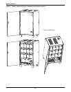
The installation of a multi-module UPS configuration must follow the installation procedure for a sin-
gle UPS module with the additional requirements detailed in this chapter.
In addition to the local EPO push button on the front panel of the UPS module (that stops operation of
that module), the UPS supports also a remote emergency stop to permit simultaneous multi-module
shutdown.
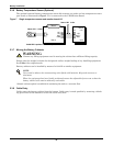
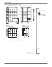
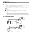
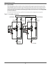
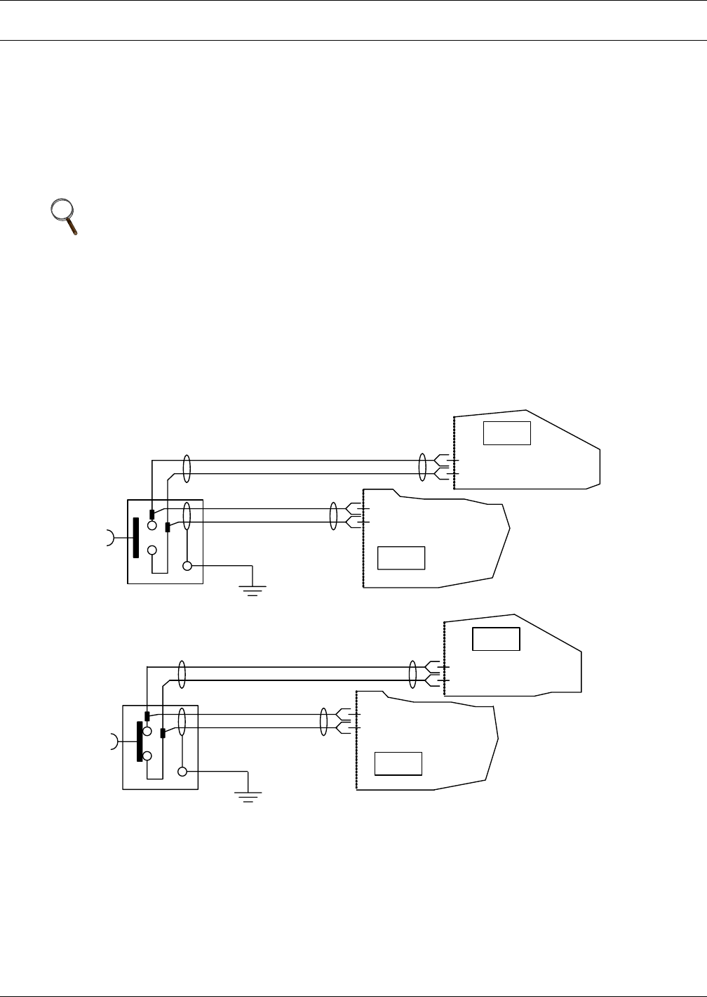
Figure 13 Emergency power off connections
NOTES
1. The remote emergency power off switch must be voltage-free and Normally Open or
Normally Closed.
2. The open voltage supplied is 12VDC, < 20mA
3. This external emergency stop may be supplied with a second set of contacts that can be used
to trip incoming mains or bypass supply circuit breakers supplied by others and fitted with
remote trip units.
4. Normally Closed EPO - X2: 1&2, these terminals are supplied factory-linked on the monitor
board.
UPS2
UPS1
Monitor Board
Monitor Board
X2:1
X2:2
X2:1
X2:2
EPO
UPS1
X2:3
X2:4
Monitor Board
UPS2
X2:3
X2:4
Monitor Board
EPO