


Operating Procedures
45
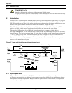
6.0 OPERATING PROCEDURES
6.1 Introduction
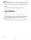
The NX can operate in any of four modes, as shown in Table 9. This section provides instructions on
switching between modes, resetting the UPS, switching the inverter On and Off and performing other
operations.
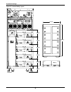
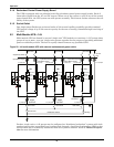
6.1.1 Power Switches
The UPS unit power switches are CB1 and SW1.
• CB1-Input Current Breaker. Connects the utility supply to the UPS input.
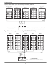
• SW1 - Rotary switch. Has four positions—NORMAL, BYPASS, TEST and MAINT—that corre-
spond to different positions of the SW1-A/B/C/D.
The positions of the rotary switch (SW1) are:
• SW1-A—Output Isolator. Connects the output of the UPS to the load.
• SW1-B—Neutral Isolator. Connects neutral to the UPS.
• SW1-C—Bypass Isolator. Connects the UPS with the bypass supply.
• SW1-D—Maintenance Bypass Isolator. Permits supply of the load directly by the bypass line for
maintenance of the UPS unit.
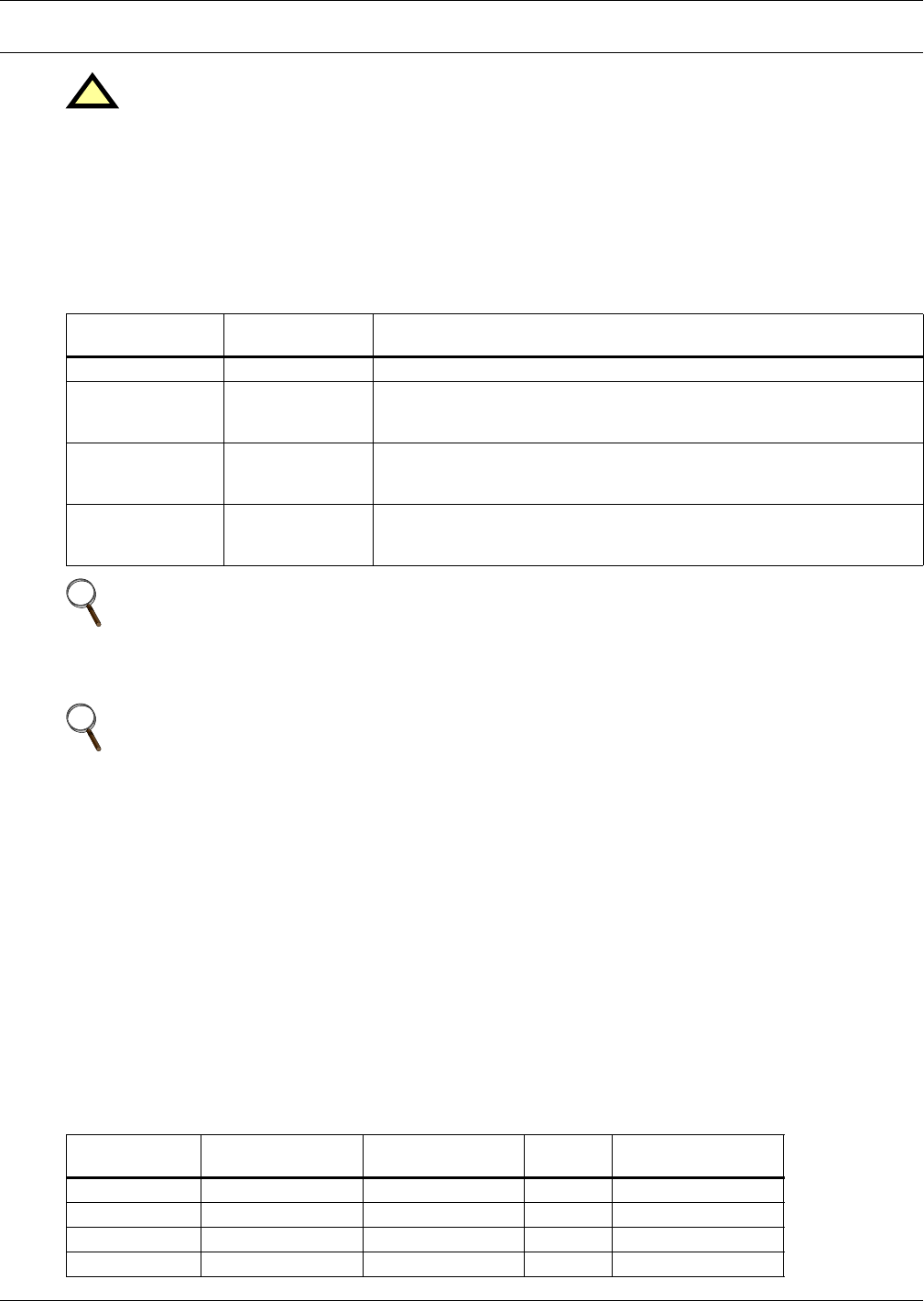
The functions of the rotary switch are shown in Table 10.
!
WARNING
Hazardous mains and / or battery voltage present behind covers.
No user-serviceable parts are located behind covers that require a tool for their removal. Only
qualified service personnel are authorised to remove such covers.
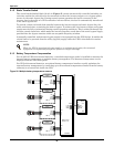
Table 9 UPS operating modes
Operating Mode
Rotary Switch
Position Description
Normal Operation NORMAL The UPS is powering the load.
On Static Bypass
BYPASS or
NORMAL
The load power is supplied through the static bypass line. This may be
considered as a temporary mode during load transfers between inverter
and maintenance bypass or supply under abnormal operating conditions.
On Test TEST
No load power is supplied by the UPS. The load is connected to utility
power via the Maintenance Bypass Supply line. NOTE: The load is not
protected against disturbances in AC input power in this mode.
On Maintenance
Bypass
MAINT
The UPS is shut down but the load is connected to utility power via the
Maintenance Bypass Supply line. NOTE: The load is not protected
against disturbances in AC input power in this mode.
NOTE
1. The user controls and indicators mentioned in these procedures are identified in 7.0 -
Operator Control Panel and Display.
2. The audible alarm may sound at various points during these procedures. It can be canceled
at any time by pressing the SILENCE ON/OFF push button.
NOTE
This unit refers to some modes and conditions that are set or adjusted using proprietary service
software. To take advantage of all the available features for the NX, the unit must be
commissioned by a Liebert factory-trained service engineer.
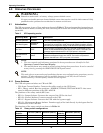
Table 10 Rotary switch configurations
Rotary Switch
Position
OUTPUT (SW1-A) BYPASS (SW1-C)
MAINT
(SW1-D)
NEUTRAL (SW1-B)
NORMAL ✔✔ ✔
BYPASS ✔✔ ✔
TEST ✔✔ ✔
MAINT ✔