


SFE2010/SFE2010P Administration Guide 8
Connecting the Cables
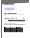
Connecting Devices
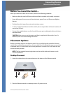
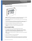
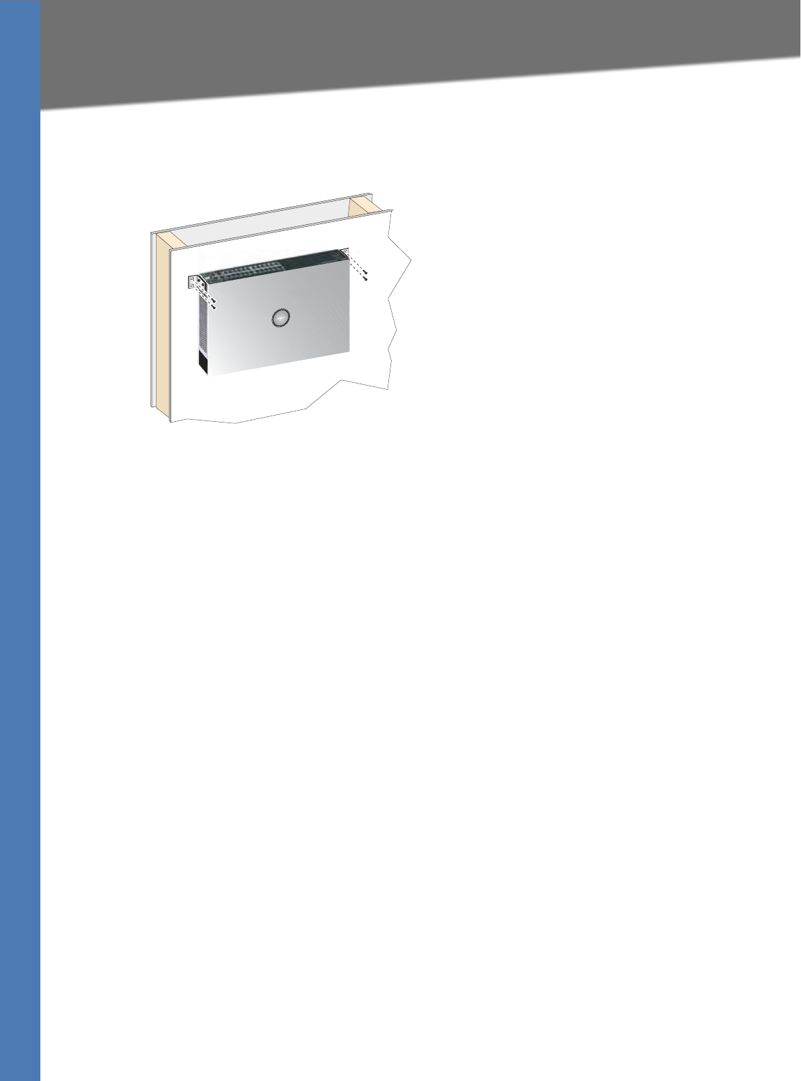
Wall-Mount Placement
1. On one of the side corners, remove the four front screws on of the Ethernet switch. Retain
the screws for re-installation.
NOTE: The Ethernet switch, shown below, is mounted with the ports located on top. When
th
e switch is mounted to a wall, the ports can be oriented in any direction.
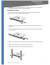
2. Place one of the supplied spacers on the side of the Ethernet switch so the four holes align
to t
he screw holes.
3. Place a rack mount bracket next to the spacer and reinstall the four screws (removed in step
1). Th
e wall mount brackets should point towards the bottom of the Ethernet switch.
4. Repeat steps 1 through 3 for the other corners of the Ethernet switch.
5. Attach the Ethernet switch to a wall with appropriate screws (not supplied).
CAUTION: En
sur
e that the Ethernet switch is securely attached to the wall.
Connecting the Cables
To connect network devices to the Ethernet switch, follow these instructions:
1. For 10/100Mbps devices, connect a Category 5 Ethernet network cable to one of the
numbe
red ports on the Ethernet switch. For a 1000Mbps device, connect a Category 5e
Ethernet network cable to one of the uplink ports on the Ethernet switch.
NOTE: I
f connecting an Ethernet switch
to an SVR3000 router, connect it to a Cascade port
on the SVR3000.
2. Connect the other end to a PC or other network device.
3. Repeat steps 2 and 3 to connect additional devices.
4. If you are using the mini-GBIC port, then insert the mini-GBIC module to the mini-GBIC port.
F
o
r detailed instructions, refer to the documentation supplied with the mini-GBIC module.