


9-12
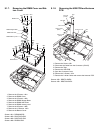
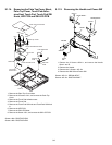
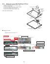
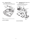
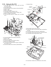
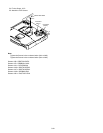
9.2.3. Setting the Inverter PCB, TS PCB and LCD Unit
1. Set the LCD Unit to the LCD Front Cabinet in order.
2. Attach the 2 drop holders.
3. Connect the Cable to the Connector. (CN200,CN201)
4. Connect the 3 Cables to the 3 Connectors.
5. Fix the Inverter PCB using the 2 Screws. <N5>
Screws <N5>: DRQT26+D4FKL
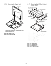
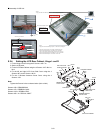
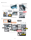
Q Preparation of Inverter
<N5>
<N5>
LCD Unit
LCD Front Cabinet
Inverter PCB
TS PCB
LCD Drop Holder
LCD Drop
Holder
A
B
A
B
C
C
to Connector
(CN200)
Connector
(CN200)
Connector
(CN201)
Wrap
Inverter Shield Tape
around
Inverter
Shield Case
and attach.
Ensure that
Inverter Shield Tape
does not
run over the edge of
Inverter Shield Case
.
<Inverter Shield Tapes Attachment Guide>
Protrusion by wrinkles, etc. = 0.2 or less
Air Bubble = 1 cm 2 or less / 1 bubble size
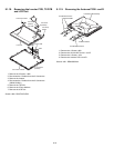
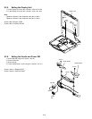
Important Parts
for Safety
Inverter-PCB
Inverter is set,
attach
Inverter Shield Case is set
Inverter Shield Case
Inverter Shield Case Outside
Attach the Inverter Shield Tape
Safety Working
* Notes:
1. Apply the load when attaching the parts. 20N to 30N (2 to 3Kgf)/cm2
2. When handling Inverter-PCB, do not bend or add impact.
Do not touch the Transformer part
when attaching to Inverter Case.
Board attachment
Match the board edge and the case edge.
Difference: 0.5mm or less
Check the part
number ’2148M1’
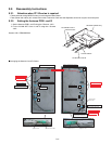
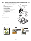
Prepare Inverter and the Inverter
shield Case Outside for Assysite.
Attach it putting the protrusion mark next to the caution label.