


9-29
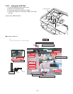
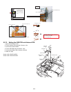
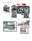
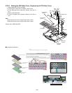
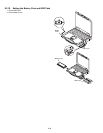
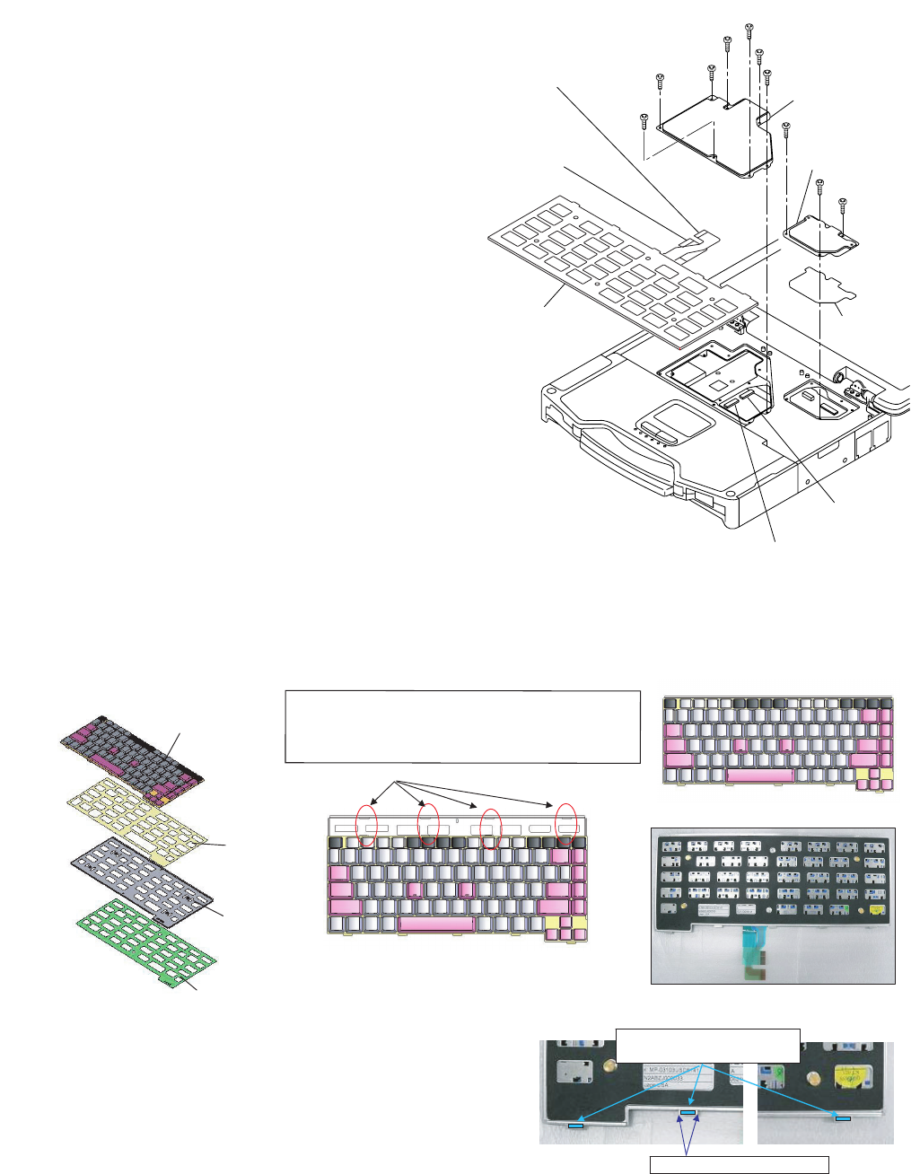
9.2.16. Setting the KB Cable Cover, Keyboard and LCD Cable Cover
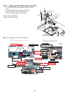
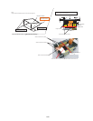
1. Set the Keyboard onto the Computer.
2. Connect the 2 Cables to the 2 Cables. (CN13,CN14)
3. Fix the KB Cable Cover using the 7 Screws. <N4> No1 to
No7
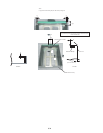
4. Set the LCD Cable Plate.
5. Fix the LCD Cable Cover using the 3 Screws. <N4> No1 to
No3
Note:
Tighten the Screws in the numbered order (No1 to No7).
Tighten the Screws in the numbered order (No1 to No3).
Screws <N4>: DRQT26+D3FKL
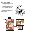
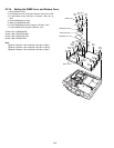
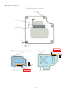
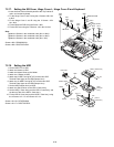
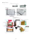
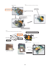
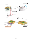
Q Arranging the Keyboard
<N4>
<N4>
<N4>
<N4>
<N4>
<N4>
<N4>
<N4>
<N4>
<N4>
to Connector
(CN14)
Connector
(CN13)
Connector
(CN14)
to Connector
(CN13)
KB Cable Cover
LCD
Cable Cover
LCD
Cable Plate
Keyboard
No.6
No.4
No.1
No.5
No.3
No.7
No.2
No.1
No.2
No.3
Attach the Keyboard
Spacer Tape
Attach the Keyboard
Spacer Sheet
Attach the Keyboard
Back Plate
Keyboard US is installed
Attach the Keyboard Fook Spacer Lower
Plate hole
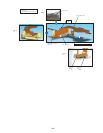
* Notes:
1. Apply the load when attaching the parts. 20N to 30N (2 to 3Kgf)/cm2
1. Attach the Keyboard US and Keyboard Spacer. (KB Preparation)
2. Attach the Keyboard Back Plate and Keyboard Spacer Sheet. (Plate Preparation)
(Ensure Keyboard Spacer Sheet does not run over the level of Keyboard Back Plate.)
3. Attach the prepared KB to the prepared plate.
(Insert the KB protrusions into the plate holes and determine the position.)
: Fit to the edge of plate (KBD back plate).
Both sides should not come over the plate.