


9-15
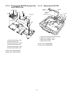
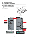
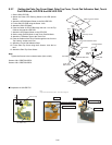
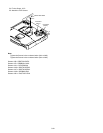
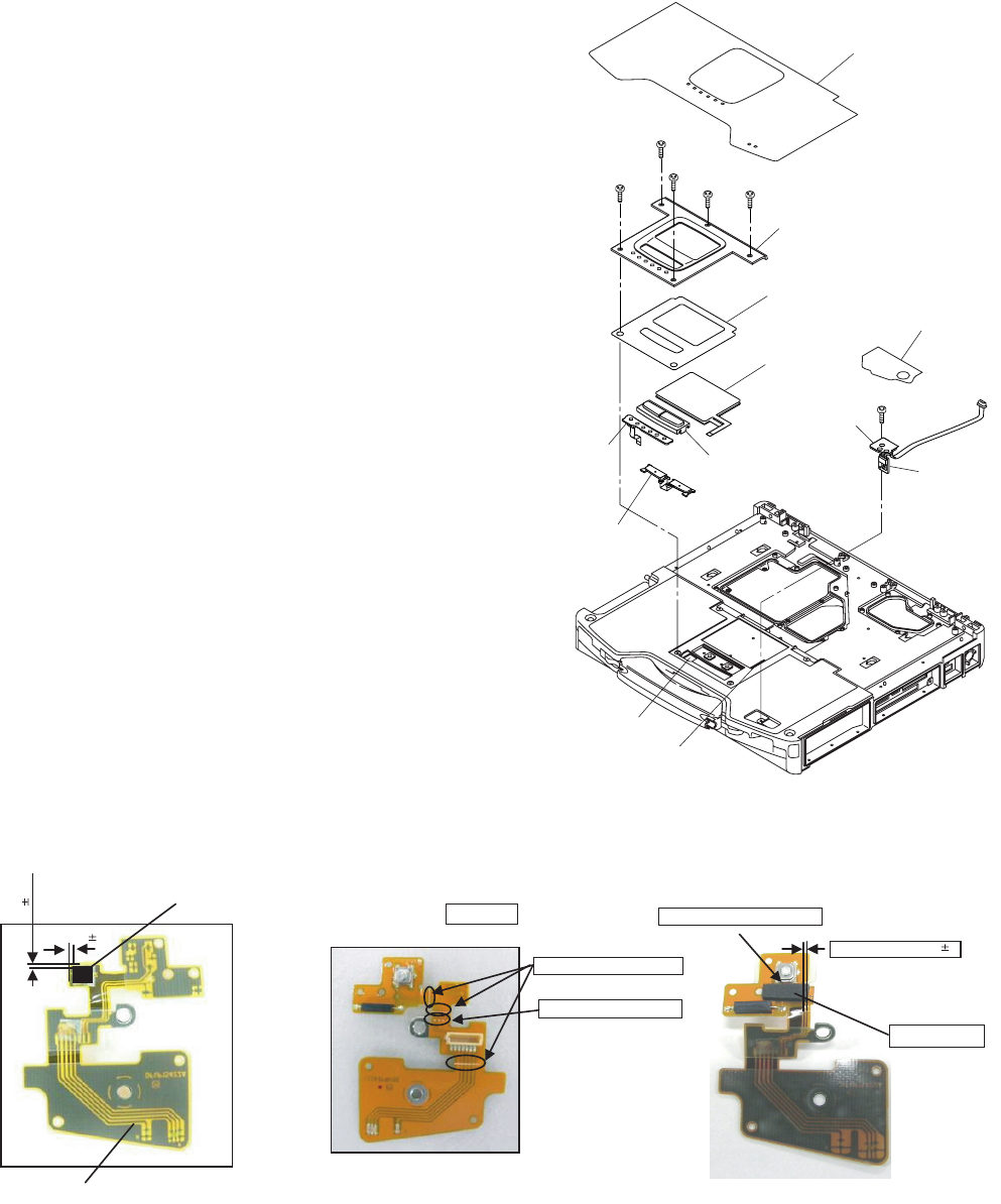
9.2.7. Setting the Palm Top Cover Sheet, Palm Top Cover, Touch Pad Adhesion Seat, Touch
Pad SW Knob, LED PCB And SW LED PCB
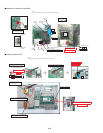
1. Set the SW LED PCB.
2. Attach the Power LED Packing Sheet to the LED Spacer
Sheet.
3. Attach the LEDX6 Spacer Sheet on the SW LED PCB.
4. Fix the SW LED PCB using the Screw. <N5>
5. Attach the PW LED Sheet.
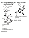
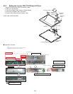
6. Pass the Cable of LED PCB through the hole 1 on the Top
Cabinet, then set the LED PCB.
7. Attach the LES Spacer Sheet on the LED PCB.
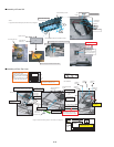
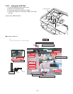
8. Set the touch Pad SW Knob In and Touch Pad SW Knob
9. Attach the TP Bottom Tape to the Touch Pad.
10. Pass the Cables of the Touch Pad through the hole 2 on the
Top Cabinet, set the touch Pad.
11. Attach the Touch Pad Adhesion Seat.
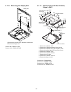
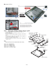
12. Fix the Palm Top Cover using the 5 Screws. <N4> No1 to
No5
13. Attach the Palm Top Cover Sheet.
Note:
Tighten the Screws in the numbered order (No1 to No5).
Screws <N4>: DRQT26+D3FKL
Screws <N5>: DRQT26+D4FKL
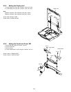
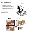
Q Preparation of SW LED FPC
Palm Top Cover Sheet
<N4>
<N5>
Palm Top Cover
PW LED Sheet
Touch Pad Adhesion Seat
Touch Pad
LED PCB
Touch Pad SW Knob
Touch Pad
SW Knob In
PW LED
PCB
SW LED
PCB
<N4>
<N4>
<N4>
<N4>
No.4
No.2
No.5
No.3
No.1
Hole 1
Hole 2
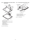
0.5 0.5
1 1
Attach the Tape
Attach the Sheet
* Notes:
1. Apply the load when attaching the parts. 20N to 30N (2 to 3Kgf)/cm2
Use a pinset.
White Full Line : Mountain Fold
Attach it not to overlap the SW leg.
Flex Notch Standard 0 1
White Dotted Line : Valley Fold
SW-LED FPC Ass’y