


9-24
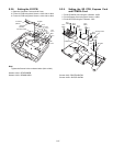
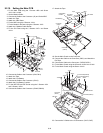
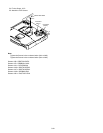
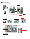
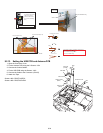
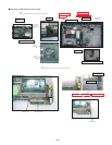
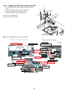
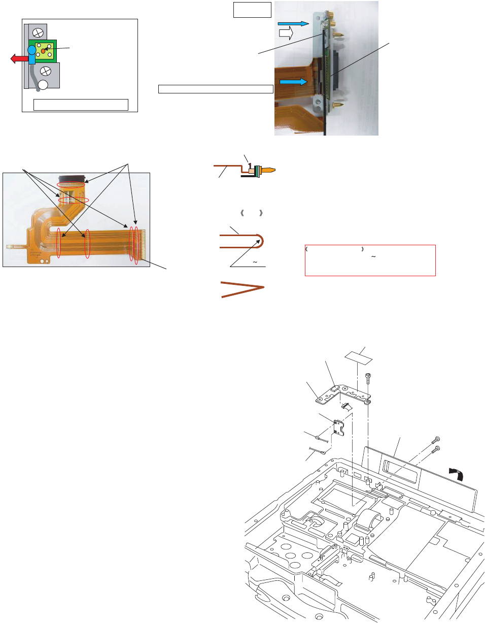
9.2.13. Setting the USB PCB and Antenna PCB
1. Open the Connector Cover.
2. Fix the Antenna PCB using the 2 Screws. <N3>
3. Connect the 2 white Cables.
4. Fix the USB PCB using the Screws. <N5>
5. Connect the Cable to the Connector. (CN100)
6. Attach the Tape.
Screws <N3>: DRQT2+G6FKL
Screws <N5>: DRQT26+D4FKL
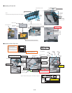
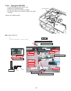
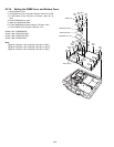
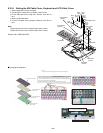
FPC
The attention of folding : Breakage countermeasure.
1,The bending inside is R0.5 1
2,Don’t mistake a bending direction.
Don’t use a mistaken thing.
(R0.5 1)
NG
OK
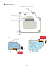
Figure seen from direction of arrow of A
The terminal of the antenna
cable must not come in
contact with this terminal.
(Put it on the metal fittings
side. )
Cable
Relay Circuit Board Ass’y
Insert FPC into Relay Circuit Board Ass’ys socket
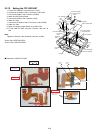
FPC
Mountain Fold (
Straight Line
)
Valley Fold (
Dotted Line
)
Insert the Plug
into the Socket
Lock after FPC insertion
FIG
FPC
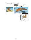
A
<N3>
<N3>
<N5>
USB PCB
Connector
(CN100)
Antenna PCB
Connector Cover
Antenna Cable
(White)
Antenna Cable
(White)
Tape