


9-17
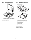
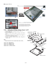
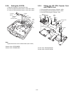
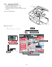
9.2.8. Setting the I/O PCB
1. Open the Connector Cover and Lid Cover.
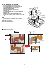
2. Fix the I/O PCB using the 4 Screws. <N15> No1 to No4
3. Fix the I/O PCB using the 4 Screws. <N14> No1 to No4
Note:
Tighten the Screws in the numbered order (No1 to No4).
Screws <N14>: DFHE5058ZB
Screws <N15>: DRHM5104ZA
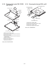
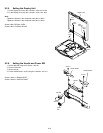
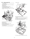
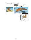
9.2.9. Setting the SD PCB, Express Card
and PCMCIA Card
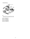
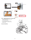
1. Fix the PCMCIA Card using the 4 Screws. <N22>
2. Fix the Express Card using the 4 Screws. <N22>
3. Fix the SD PCB using the 2 Screws. <N5>
Screws <N5>: DRQT26+D4FKL
Screws <N22>: DXQT2+G4FNL
Connector
(CN701)
Connector
(CN700)
I/O PCB
LID
Cover
Connector Cover
<N15>
No.3
<N15>
No.1
<N14>
No.1
<N14>
No.3
<N14>
No.4
<N15>
No.4
<N14>
No.2
<N15>
No.2
<N22>
<N22>
<N22>
<N22>
<N22>
<N22>
<N22>
<N5>
<N5>
SD PCB
Express Card
PCMCIA Card
No.2
No.1
No.3
<N22>
No.4
No.1
No.2
No.3
No.4
No.1
No.2