


9-18
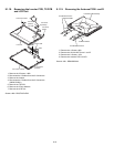
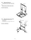
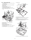
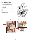
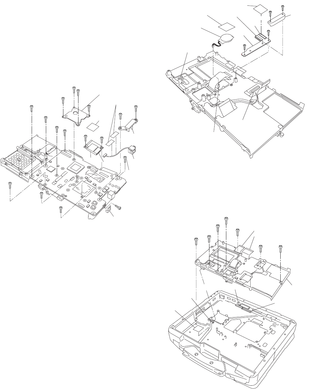
9.2.10. Setting the Main PCB
1. Fix the Main PCB using the 7 Screws <N5> and Screw.
<N11> No1 to No8.
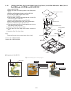
2. Set the Modem Cable.
3. Connect the Cable to the Connector (J2) and fix the MDC.
4. Attach the Tape.
5. Attach the 1394 Sheet.
6. Fix the MDC using the 2 Screws. <N11>
7. Fix the Modem LAN Case using the 2 Screws. <N5>
8. Attach the 2 Modem Cable Sheets.
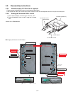
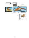
9. Fix the ICH Plate using the 3 Screws <N17> and Screw
<N11>.
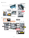
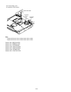
10. Connect the Cable to the Connector (CN4,CN11)
11. Attach the Tape.
12. Attach the Coin Battery.
13. Connect the Cable to the Connector. (CN19)
14. Attach the Coin Battery Cushion.
15. Fix the MP PCB and MP Guide using the 2 Screws <N5>
and 2 Screws. <N21>
16. Connect the Cable to the Connector. (CN400,CN401)
17. Attach the Tape.
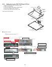
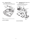
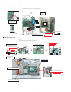
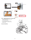
18. Set the Main Chasis on the Computer.
19. Connect the Cable to the Connector (CN31) and Attach the
Pet Tape.
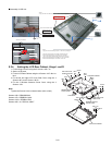
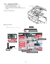
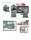
20. Connect the Cable to the Connector. (CN700,CN701)
21. Fix the Main Chasis using the 6 Screws <N16> No1 to No6
22. Fix the Main Chasis using the Screw. <N18>
23. Connect the 2 Cables to the 2 Connectors. (CN17,CN27)
<N5>
<N5>
<N17>
<N11>
<N11>
<N11>
<N17>
<N17>
<N5>
<N5>
<N5>
<N5>
<N5>
<N5>
<N5>
1394 Sheet
Modem
Cable
Connector
(J2)
MDC
Modem
LAN Case
Modem
Cable Sheet
Tape
ICH Plate
<N11>
<N5>
No.3
No.2
No.5
No.4
No.6
No.7
No.1
No.8
<N5>
<N21>
<N21>
<N5>
Connector
(CN4)
Connector
(CN11)
Connector
(CN400)
Connector
(CN401)
Coin Battery
MP PCB
MP Guide
Connector
(CN19)
Coin Battery
Cushion
Tape
<N16>
<N16>
<N16>
<N18>
<N16>
<N16>
<N16>
Connector(CN701)
Connector
(CN31)
Pet Tape
Connector(CN700)
Main Chasis
to Connector(CN701)
to Connector(CN700)