


9-13
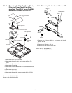
Q Assembly of LCD Unit
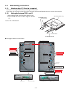
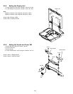
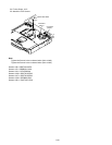
9.2.4. Setting the LCD Rear Cabinet, Hinge L and R
1. Fix the Hinge L and R using the 2 Screws. <K9-1-4>
2. Set the LCD Latch.
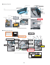
3. Fix the LCD Rear Cabinet using the 4 Screws. <N7> No1 to
No4
4. Fix the left and right LCD Cover Side Cover using the 4
Screws <N7> and 2 Screws. <N13>
5. Fix the 2 Wireless Antenna Corner Cover using the 4
Screws. <N7>
Note:
Tighten the Screws in the numbered order (No1 to No4).
Screws <N2>: DRHM5054XA
Screws <N7>: DRSB26+10HKL
Screws <N13>: DRSB4+10FKL
Screws <K9-1-4>: DRYN4+J10KLT
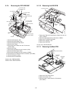
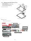
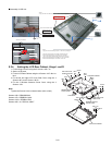
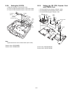
Attach the TS Controller
Attach the
Inverter
MIL Shierd
0 0.5mm
LCD Front Ass’y
LCD Drop Holder Insertion
LCD Drop Holder Insertion
* Notes:
1. Apply the load when attaching the parts. 20N to 30N (2 to 3Kgf)/cm2
Confirm that the LCD
Cushion is not wrapped.
Match to the LCD
edge and attach it.
Clearance : 2 mm or less
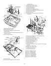
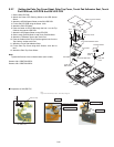
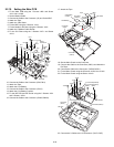
1. Insert the TS Flex into the TS Controller, and attach the tape.
2. Remove the Release Paper A and attach the TS Controller.
(Do not come off the sheet and apply the pressure on the LCD.)
3. Remove the Release Paper B and attach it on the TS Controller.
4. Remove the Release Paper C and attach it on the LCD.
1. Apply the load when attaching the parts. 20N to 30N (2 to 3Kgf)/cm
* Notes:
Flex Stiffening Plate Edge
TS Flex Insertion
Attach the Tape
Release Paper A
Release Paper B
Release Paper C
<N7>
<N7>
<N7>
<N7>
<N7>
<N7>
<N7>
<N7>
<N7>
<N7>
<N13>
<N13>
<N7>
<N7>
LCD Latch
LCD Rear Cabinet
Wireless Antenna
Corner Cover
left LCD Cover
Side Cover
right LCD Cover
Side Cover
Wireless Antenna
Corner Cover
LCD Front Cabinet
Hinge L
Hinge R
No.1
No.2
No.4
No.3
<K9-1-4>
<K9-1-4>