


9-28
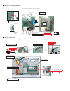
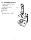
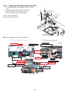
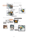
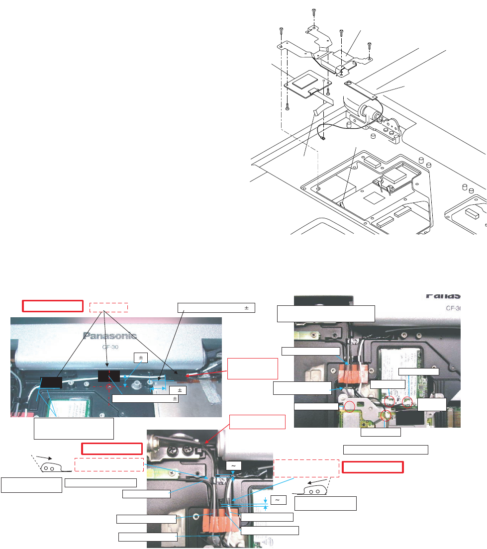
9.2.15. Setting the GPS PCB and Bluetooth PCB
1. Fix the GPS BT Angle and GPS PCB using the 2 Screws.
<N11>
2. Connect the Cable to the Connector on GPS PCB.
3. Fix the GPS Ass’y using the 4 Screws. <N12>
4. Connect the Cable to the Connector. (CN25)
Screws <N11>: DFHE5025XA
Screws <N12>: DXQT2+F3FNL
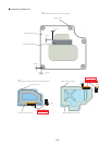
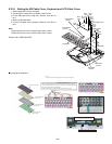
Q Cautions for Setting GPS ASSY and BT PCB ASSY
GPS PCB
Bluetooth
PCB
Connector(CN25)
<N11>
<N11>
GPS BT Angle
<N12>
<N12>
<N12>
<N12>
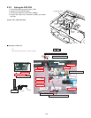
to Connector
(CN25)
Safety Working
Safety Working
Safety Working
8 1
10 2
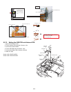
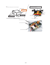
Main Antenna
Sub Antenna
Bluetooth Cable
Whip Antenna Cable
Whip Antenna Cable
Main Antenna Cable
GPS Antenna Cable
0 2
0 2
Sub Antenna Cable
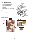
* Notes:
* Notes:
1. Apply the load when attaching the parts. 20N to 30N (2 to 3Kgf)/cm2
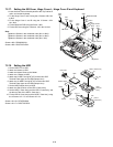
Fit to the plate squeeze line. 1
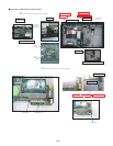
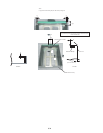
Attach the Tape
Put the Cable along
the Cabinet side and
tape it firmly.
Match to the boss center.
Cabinet Level Standard
Tolerance 0 to 1
Process the wire into the groove.
Pass the Cable behind
the Cabinet protrusion.
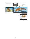
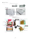
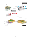
Attach the Cable Sheet into
Main Cable and Whip Cable.
Attach the Cable Sheet into
Sub Cable and GPS Cable.
Ensure that the wrapping
direction is right.
Avoid coming over the groove.
Ensure that the wrapping
direction is right.
Connect into the coaxial Connector.
Process the wire to the
back from the aperture.
Insert the
cable plug.
Process the wire of whip ANT cable from
LCD to the back from the aperture.
1. Do not gouge when inserting and removing the plug.
2. Do not damage the coating when handling the cable.
Bluetooth Cable
GPS Antenna