


9-21
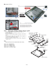
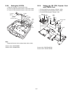
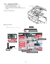
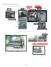
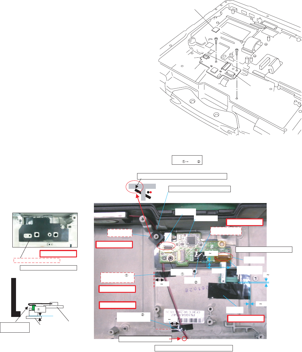
9.2.11. Setting the PAD PCB
1. Fix the PAD PCB using the 2 Screws. <N4>
2. Attach the TP PCB Screw Sheet.
3. Connect the Cable to the Connector. (CN802)
4. Connect the Cable to the Connector (CN801) and attach
the Tape.
Screws <N4>: DRQT26+D3FKL
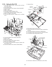
Q Assembly of PAD PCB
<N4>
<N4>
Pad PCB
Connector
(CN802)
Connector
(CN801)
Tape
TP PCB Screw Sheet
Safety Working
Safety Working
Safety Working
Safety Working
Safety Working
Safety Working
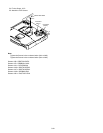
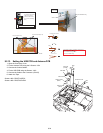
Attach the
Cable Sheet
0 2
LED PCB
Attach the Touch Pad INS Sheet
0 2
7 11
7 11
0 2
0 2
FFC Insertion
FFC Insertion
Attach the Touch
Pad FFC Fix Tape
Tighten of
Screw
Tighten of
Screw
Attach the Touch Pad
PCB Screw Sheet
Cable Hold Sheet
is installed
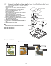
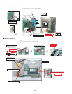
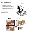
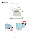
* Notes:
1. Apply the load when attaching the parts. 20N to 30N (2 to 3Kgf)/cm2
Avoid running over the boss and the rib.
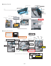
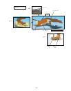
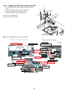
Process the surplus
of FFC to the back.
Screw Screw
Insert the boss at an angle to put here close to the Cabinet side.
Process the SP cable between the bosses.
PCB Pad is set
Attach the Tape
Fit to the Cabinet line.
Attach the Tape
Fit to the Cabinet line.
Process the wire targeting the boss.
Do not insert the Connector at an angle.
Order of fixing
PCB Pad
CN Connection After connecting, add the kapton tape.