


DS33Z41 Quad IMUX Ethernet Mapper
31 of 167
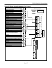
8.8 Serial Interface
The Serial Interface consists of physical serial port, IMUX/IBO Formatter, and HDLC/X.86 engine. The Serial
Interface supports time-division multiplexed serial data, in a format compatible with Dallas Semiconductor’s
8.192Mbps Channel Interleaved Bus Operation (IBO). The Serial Interface receives and transmits the
encapsulated Ethernet packets. The physical interface consists of Transmit Data, Transmit Clock, Transmit
Synchronization, Receive Data, Receive Clock, and Receive Synchronization. The Serial Interface can be
seamlessly connected to the IBO bus of the Dallas Semiconductor/Maxim T1/E1/J1 Framers and Single-Chip
Transceivers (SCT’s) such as the DS21Q42, DS21Q44, DS2155, and DS21458. Functional timing is shown in
Figure 11-9
.
• Byte-aligned data is always input through the RSER pin at a rate of 8.192Mbps. RSYNC is an 8kHz
reference input used to determine the position of channel 1 for the first T1/E1 link. If the device is
configured to use less than 4 T1/E1 links, the data on RSER associated with the unused links must
be filled with “all ones”.
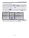
• Data on the IBO bus is byte-interleaved (by channel) for up to 4 T1/E1 interfaces, and is “byte-striped”
across the available links. The Channel 1 byte arrives (MSB first) for all four T1/E1 links, followed by
the Channel 2 byte for all four T1/E1 links, etc.
• Channel 1 is never used for data. In T1 mode, channels 5, 9, 13, 17, 21, 25, 29 are also not used for
data. Bytes for all unused timeslots will be replaced with FFh. All 4 TDM links must be configured for
T1 operation, or all 4 links must be configured for E1 operation.
• Channel 2 is a reserved for link management and coordination. This timeslot is used for inter-node
communication to initiate, control, and monitor the IMUX function. The IMUX operation is initiated with
a handshaking procedure and if successful, followed by a data phase. There is no data transfer
during the handshaking phase. During data transfer, channel 2 is used to provide frame sequence
numbers. The receiver uses the sequence numbers (0-63) to reassemble the frames to compensate
for a differential delay of up to 7.75ms. If the differential delay exceeds 7.75ms, packet errors will
occur.
• Byte-aligned data is output on the TSER pin at a rate of 8.192Mbps. TSYNC is used as an 8kHz
synchronization for the TSER data and is used to determine the position of channel 1 for the first
T1/E1 link. If the device is configured to use less than 4 T1/E1 links, data bytes on TSER associated
with the unused links are set to FFh.
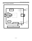
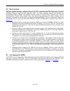
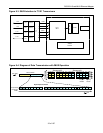
8.9 Link Aggregation (IMUX)
The DS33Z41 has a link aggregation feature that allows data from the Ethernet interface to be inverse multiplexed
over up to 4 bonded T1/E1 links. The T1/E1 data streams are input and output from the DS33Z41 on an
8.192Mbps Interleaved Bus (IBO). The IMUX function is shown graphically in Figure 8-3
and Figure 8-4.