


DS33Z41 Quad IMUX Ethernet Mapper
34 of 167
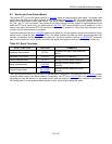
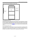
8.9.2 IMUX Command Protocol
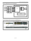
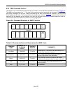
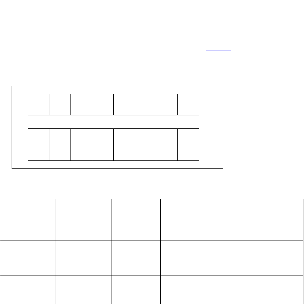
The format for all commands sent and received in Channel 2 of the IBO Serial Interface is shown in Figure 8-5.
The MSB for all commands is a “1”. The next 6 bits contain the actual opcode for the command. The LSB is the
even parity calculation for the byte. These commands will be sent and received on Channel 2 of each of the
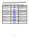
T1/E1 interleaved IBO data. The commands that are possible are outlined in Table 8-3
. Note that the 4 portions of
the IMUX link are separate and the Channel 2 for each link will send and receive commands specific to that link.
The microprocessor can disable links that are not to be aggregated.
Figure 8-5. Command Structure for IMUX Function
"1"
Command
Even
Parity
M
S
B
L
S
B
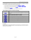
Table 8-3. Commands Sent and Received on the IMUX Links
COMMAND
NAME
COMMAND BYTE
(P IS EVEN
PARITY)
TRANSMIT/
RECEIVE
COMMENTS
Link Start 1000 001P Tx or Rx
Initiate the link. The receiver will then search for 3
consecutive sequence numbers.
Sequence 1sss 010P Tx or Rx
“sss” contains the frame sequence number for
packet segmentation and reassembly.
Rsync 1000 011P Tx or Rx
This command is sent to indicate to the distant
node that link synchronization has been achieved.
OOF 1000 100P Tx or Rx
The transmitting device has detected an out of
frame condition.
Nop 1111 111P Tx or Rx No operation.