


Page 12 - 34020201EN/AB
2. Installation
Specifications for protection devices and cables are provided in section 6 (Appendices, technical data sheet).
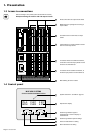
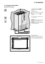
To access the connections, see section 1.3. Connection cables are not supplied.
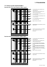
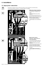
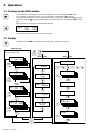
2.2 Input power connections
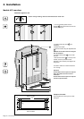
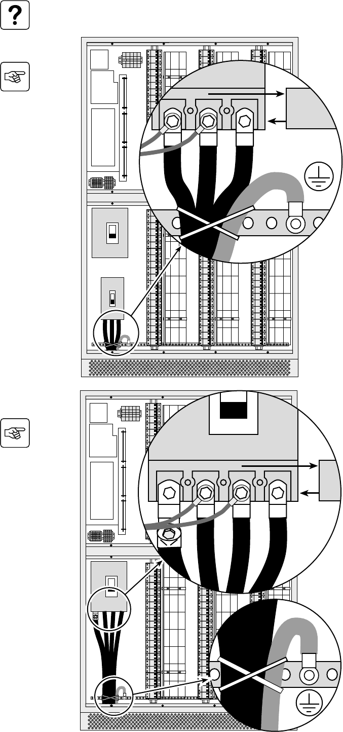
Module with isolation transformer
1. Connect the PE or PEN protection cable
to the earthing bar at the bottom of the
module.
2. Remove the bottom cover on circuit
breaker Q1.
3. Connect the three phases of the input
power cable to the bottom terminals of circuit
breaker Q1 (without removing the control
wires that are already connected).
4. Ties the cables to the earthing bar.
5. Refit the bottom cover on circuit breaker
Q1.
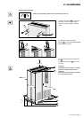
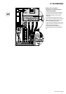
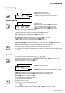
Module without isolation
transformer, separate earth and
neutral (TNS system)
1. Connect the PE protection cable to the
earthing bar at the bottom of the module.
2. Remove the bottom cover on circuit
breaker Q2.
3. Connect the three phases and the neutral
of the input power cable to the bottom
terminals of circuit breaker Q2 (without
removing the control wires that are already
connected).
4. Ties the cables to the earthing bar.
5. Refit the bottom cover on circuit breaker
Q2.
Q2
Q1
2
1
4
5
BCA
Q1
333
PE / PEN
Q2
4
1
BCNA
PE
BC
Q2
2
333
5
3
N
A