


34020201EN/AB - Page 15
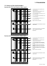
Q2
Q1
RS-232
RS-485
1
2
3
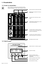
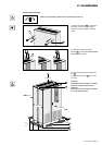
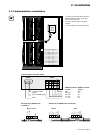
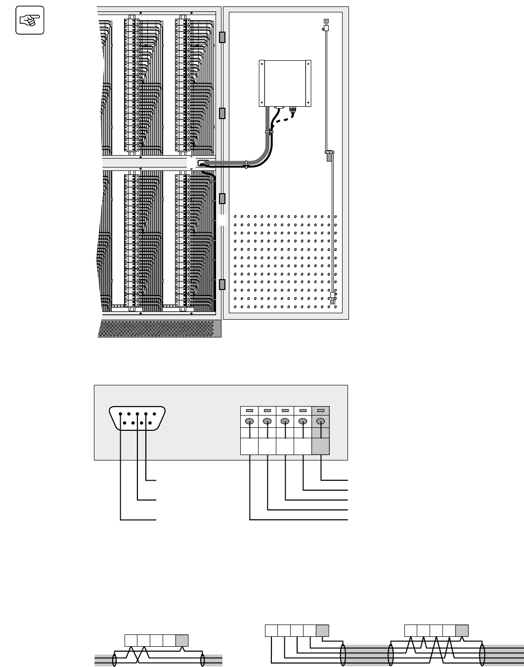
2. Installation
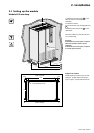
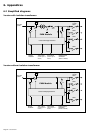
2.5 Communication connections
1. Connect the communication cable to the
RS232 or RS485 connector on the right-
hand door of the module.
2. Run the cable as shown in the figure
opposite.
3. Tie the cable down to the module frame.
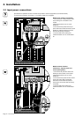
Communication connector details
RS485 connector
2 wires
GND
Tx+
Tx-
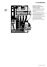
Tx+ / Rx+
Tx- / Rx-
RS485 connector
4 wires
GND
Rx+
Rx-
Not used
Not used
Td (from the PMM
display)
Rd (to the PMM display)
GND
RS232 connector
RS-485
RS-232
12345
6
7
8
9
54321
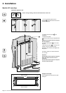
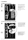
Example of an RS485 2-wire
connection:
Example of an RS485 4-wire connection:
Master SlaveMaster or slave
54321
Tx- / Rx-
Tx+ / Rx+
GND
54321
Rx-
Rx+
GND
Tx-
Tx+
Rx-
Rx+
GND
Tx-
Tx+
54321