


34020201EN/AB - Page 5
Contents
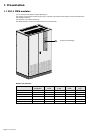
1. Presentation
1.1 250 A PMM modules .................................................................................................................... 6
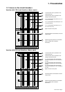
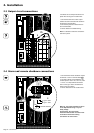
1.2 Access to the circuit breakers ................................................................................................... 7
Version with 126 circuit breakers (doors open) ............................................................................... 7
Version with 60 circuit breakers (doors open) ................................................................................. 7
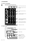
1.3 Access to connections ............................................................................................................... 8
1.4 Control panel ................................................................................................................................. 8
2. Installation
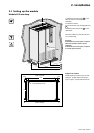
2.1 Setting up the module .................................................................................................................. 9
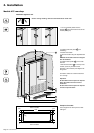
Module 825 mm deep ..................................................................................................................... 9
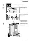
Module 425 mm deep ................................................................................................................... 10
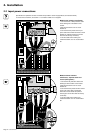
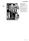
2.2 Input power connections ........................................................................................................... 12
2.3 Output circuit connections ........................................................................................................ 14
2.4 Alarm and remote shutdown connections ............................................................................... 14
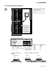
2.5 Communication connections..................................................................................................... 15
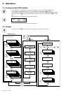
3. Operation
3.1 Turning on the PMM module ...................................................................................................... 16
3.2 Display ......................................................................................................................................... 16
3.3 Metering ....................................................................................................................................... 16
Output-circuit metering.................................................................................................................. 17
General metering .......................................................................................................................... 17
3.4 Alarms .......................................................................................................................................... 17
3.5 Setup ............................................................................................................................................ 18
Communication settings................................................................................................................ 18
Operation settings (display and alarms) ....................................................................................... 18
3.6 Turning off the PMM module ...................................................................................................... 18
4 Maintenance
4.1 Trouble-shooting and solutions ................................................................................................ 19
5 Environment .................................................................................................................................... 20
6. Appendices
6.1 Technical data sheets ................................................................................................................. 21
Electrical characteristics ............................................................................................................... 21
Thermal characteristics ................................................................................................................. 21
Noise level .................................................................................................................................... 21
Maximum wire sizes for terminal blocks ....................................................................................... 21
Recommended upstream protection devices................................................................................ 21
Standards...................................................................................................................................... 21
6.2 Simplified diagrams .................................................................................................................... 22
Version with isolation transformer ................................................................................................. 22
Version without isolation transformer ............................................................................................ 22
6.3 Auxiliary contact functions ........................................................................................................ 23
6.4 Modbus communication information ........................................................................................ 23
Access to communicated information ........................................................................................... 23
Cards BCM1, BCM2 and BCM3 (status and measurements for 42 or 21 output circuits) ............ 24
Card MCM (general status and measurements) ........................................................................... 31
6.5 Glossary....................................................................................................................................... 32
6.6 Index............................................................................................................................................. 33