


34020201EN/AB - Page 23
6. Appendices
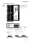
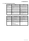
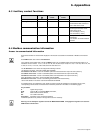
6.3 Auxiliary contact functions
Normal operation
Downgraded operation
Overload or overvoltage
Other fault
Type 2-alarm
contact
OFF
OFF
OFF
ON
Cause
Current on at least one output
circuit between 60% and 80% of
max. value for the circuit.
◗ Current on at least one output
circuit higher than 80% of max.
value for the circuit,
◗ or overvoltage (> 457 V),
◗ or overcurrent (> 250 A).
◗ Temperature rise in the isolation
transformer,
◗ or actuation of remote shutdown
function.
Alarm LED
17
Green
Yellow
Red
Red
Type 1-alarm
contact
OFF
ON
ON
OFF
Access to communicated information
Each status indication or measurement displayed on the module is accessible via the RS232 or RS485 communication
port.
Each PMM module uses a series of 16 addresses.
If the network communicates with a number of PMM modules, use an available series among the following series of 16
addresses for each module: 1 to 16 ,17 to 32, 33 to 48, 49 to 64, 65 to 80, 81 to 96, 97 to 112, 113 to 128, 129 to 144, 145
to 160, 161 to 176, 177 to 192, 193 to 208, 209 to 224 and 225 to 241.
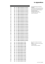
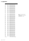
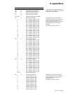
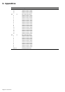
The 16 addresses in each series are assigned the following functions:
1st address in the series: reserved for MGE UPS SYSTEMS,
2nd address in the series: access to card BCM1 (status and measurements for output circuits of phase A),
3rd address in the series: access to card BCM2 (status and measurements for output circuits of B),
4th address in the series: access to card BCM3 (status and measurements for output circuits of C),
5th to 8th address in the series: reserved for MGE UPS SYSTEMS,
9th address in the series: access to card MCM (general status and measurements),
10th to 16th address in the series: reserved for MGE UPS SYSTEMS.
As indicated above, four addresses in each series are used to access the information in the registers of four cards,
corresponding to all the status and measurement information presented in the tables on the following pages.
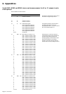
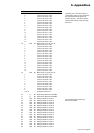
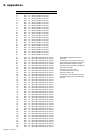
Key for tables:
# : register using 2 bytes,
R/W : read only (R ) or read/write (R/W ) information,
Bit : detail of each bit of the address,
NV : non-volatile information,
Description : description of the concerned information.
Additional explications are provided in the right-hand column if necessary.
Warning: Do not modify the registers reserved for MGE UPS SYSTEMS. Changing these registers can cause the
PMM module to malfunction.
6.4 Modbus communication information