


Page 14 - 34020201EN/AB
Q2
Q1
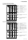
1
2
3
4
5
6
1
2
3
3
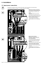
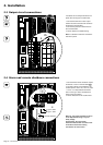
2. Installation
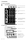
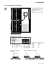
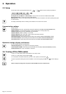
2.3 Output circuit connections
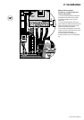
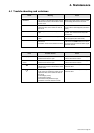
2.4 Alarm and remote shutdown connections
1. Connect the NO remote shutdown contact
to terminals 1 and 2 on terminal block 13 .
2. The alarm signals are transmitted by dry
contacts (Umax = 250 V AC / 30 V DC, Imax
= 7 A AC / 10 A DC) between terminals 3
and 4 for the type 1 alarm and between 5
and 6 for the type 2 alarm.
3. Tie the cable down to the module frame.
It is advised to use crimped ferrules on the
phase wires and lugs on the earth wires.
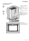
1. Connect the earth wire of each output
cable to the earth connection bar located to
the left of the metal trunking.
2. Connect the phase and neutral wires to
each circuit breaker.
3. Tie the cables to the metal trunking.
Note: it is advised to make the connections
from the top down.
13
Type 2 alarm
Type 1 alarm
Remote shutdown
Q2
Q1
1
2
2
3
Ph
N
Warning: the remote shutdown function
is not implemented using a very low
safety voltage.
Consequently, the usual safety
measures must be taken to avoid all risk
of electrical shock when making
connections for this function.