


Page 16 - 34020201EN/AB
3. Operation
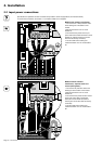
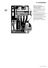
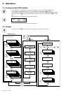
3.1 Turning on the PMM module
1. Close the upstream switching device (external and not supplied) on the circuit supplying the PMM module.
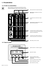
2. In a module with an isolation transformer, close ("I" or ON position) circuit breaker Q1 5 (see page 7) .
3. Make sure disconnector-fuses F1 and F2 are closed and close ("I" or ON position) circuit breaker Q2 5 (see page 7) .
◗ The system status LED 17 (see page 8) flashes yellow a few seconds, then green and should subsequently remain
green.
◗ After a few seconds, the first page of measurements is displayed:
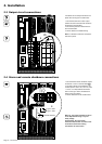
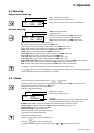
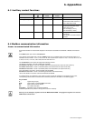
3.2 Display
4. Close the circuit breakers on the output circuits to be powered.
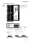
Metering mode
Alarm mode Setup mode
The display unit for the PMM module offers three operating modes: metering, alarm and setup.
This is the default mode.
Ph-A CH01 0.000
BCM CH02 0.000
BCM CH42 0.000
Ph-B CH25
WARNING
UP
Ph-C CH12
ALARM
METER
SELECT
+
UP
GENE OVER
MCM VOLTAGE
UP
UP
GENE OVER
MCM CURRENT
UP
AUX INPUT
ALARM
Enter Password :
* * * * * *
DOWN
UP
View System Info
Find Meters
Review Meters
+
UP
DOWN
SELECT
DOWN
SELECT
UP
UP
UP
Setup
Communication
UP
Setup
Operation
UP
UP
Ph-A CH01 0.000
BCM CH02 0.000
GENE KWH 0000.0
MCM KW 0000.0
METER
DOWN
UP
METER
BCM CH42 0.000
Ph-B CH01 0.000
BCM CH02 0.000
DOWN
UP
METER
BCM CH42 0.000
Ph-C CH01 0.000
BCM CH02 0.000
DOWN
UP
METER
SELECT
SELECT
SELECT
MCM MAX 0000.0
DOWN
UP
METER
METER