


Page 8 - 34020201EN/AB
Q2
Q1
MGE UPS SYSTEMS
CRITICAL POWER MONITORING SYSTEM
DOWNUP SELECT METER
NEXT
PARAMETER
PREVIOUS
PARAMETER
HOLD
READING
SCROLL
METERS
SETUP MODE
ALARM MENU
Ph-A CH01 2.637
BCM CH02 4.215
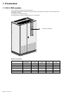
1. Presentation
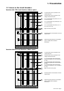
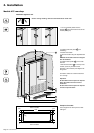
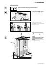
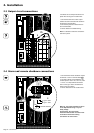
1.3 Access to connections
Remove the eight cover panels (each secured with two screws).
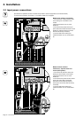
Example showing the version with 126 output circuits:
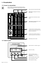
11
12
13
14
Metal trunking for passage and securing of
output cables
Connection bars for earth wires of output
cables
Terminal block for remote shutdown function
and minor and major alarms
15
In modules with an isolation transformer, of
the three input phases to circuit breaker Q1
In modules without an isolation transformer,
connection of the three input phases and the
neutral to circuit breaker Q2
10
Phase connections for output-circuit cables
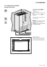
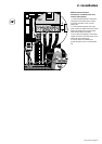
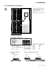
1.4 Control panel
20
17
18
22
21
19
Alphanumeric display
System status LED: see table on page 23
Scroll through different types of
measurements or return to display of
measurements
Scroll through different system settings
Previous measurement or setting
Next measurement or setting
16
Main earthing bar of the module