


34020201EN/AB - Page 17
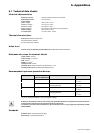
GENE KWH 0000.0
MCM KW 0000.0
Ph-A CH01 0.000
BCM CH02 0.000
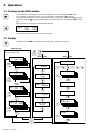
3. Operation
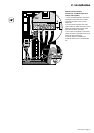
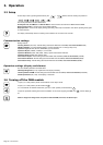
3.4 Alarms
Alarm text:
WARNING: indicates that the current on the indicated circuit (number
25, phase B) is between 60 and 80% of the maximum value.
Access alarm mode by pressing simultaneously the
SELECT
+
METER
buttons.
This mode displays the list of stored major and minor faults that have occurred in the PMM or on the output circuits.
When an alarm is present in the memory, LED 17 goes on:
◗ yellow for fault that does not hinder normal operation;
◗ red for a fault requiring intervention.
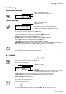
3.3 Metering
Ph-A: measurements on phase A
Display of the current drawn by the output circuit in amperes
Output-circuit metering
General metering
GENE: general measurements.
Measurement units:
KWH: total energy consumed by the PMM module in kWh.
This value can be reset via the communication function.
KW: total active power drawn by the PMM module in kW.
KVAR: reactive power drawn by the PMM module in kVAR.
The
SELECT
button may be used to hold the display of a measurement if the module is set up for autoscrolling (parameter
rotation). The display flashes and the measurement is not updated.
KVA: apparent power drawn by the PMM module in kVA.
PF: average power factor on the three phases of the PMM module.
V-LL: average phase-to-phase voltage on the three phases of the PMM module in volts.
V-LN: average phase-to-neutral voltage on the three phases of the PMM module in volts.
AMPS: average current on the three phases of the PMM module in amperes.
FREQ: frequency of the voltage supplied by the PMM module in Hertz.
KW-A, KW-B, KW-C: active power drawn by phases A, B and C of the PMM module in kW.
PF-A, PF-B, PF-C: power factor on phases A, B and C of the PMM module.
V-AB, V-BC, V-AC: phase-to-phase voltages supplied by the PMM module in volts.
V-AN, V-BN, V-CN: phase-to-neutral voltages supplied by the PMM module in volts.
AMPA, AMPB, AMPC, AMPN: current on the three phases A, B, C and on the neutral of the PMM module in amperes.
MIN: minimum power (stored in memory) supplied by the PMM module in kW since the last reset.
MAX: maximum power (stored in memory) supplied by the PMM module in kW since the last reset.
The minimum, maximum and average power values are reset via the communication function.
Ph-B CH25
WARNING
Ph-B: alarm on phase B.
CH-25: alarm on output circuit 25.
These alarms are stored in memory:
◗ Press the
SELECT
button to clear the displayed alarm.
◗ Press the
METER
button to return to metering mode.
The display automatically returns to metering mode if buttons 19 to 22 are not used for ten seconds.
ALARM: indicates that the current on the indicated circuit is higher than 80% of the maximum value.
OVER VOLTAGE: the voltage supplied by the PMM exceeds the permissible range by over 10%.
OVER CURRENT: there is an overload on the PMM.
AUX INPUT ALARM: this alarm signals either:
◗ excessive temperature rise in the isolation transformer,
◗ or activation of the remote shutdown button.
CH-01: measurements on output circuit 01