


34020201EN/AB - Page 29
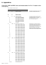
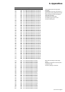
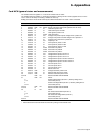
# Bit R/W NV Description
268 W Global circuit breaker rating
269 W Global minor alarm threshold (%)
270 W Global major alarm threshold (%)
271 W Global minor alarm time delay
272 W Global major alarm time delay
273 to 280 Reserved for MGE UPS SYSTEMS
281 R Non-stored minor alarms
0 60% < Current in circuit 01 < 80%
1 60% < Current in circuit 02 < 80%
2 60% < Current in circuit 03 < 80%
3 60% < Current in circuit 04 < 80%
4 60% < Current in circuit 05 < 80%
5 60% < Current in circuit 06 < 80%
6 60% < Current in circuit 07 < 80%
7 60% < Current in circuit 08 < 80%
8 60% < Current in circuit 09 < 80%
9 60% < Current in circuit 10 < 80%
10 60% < Current in circuit 11 < 80%
11 60% < Current in circuit 12 < 80%
12 60% < Current in circuit 13 < 80%
13 60% < Current in circuit 14 < 80%
14 60% < Current in circuit 15 < 80%
15 60% < Current in circuit 16 < 80%
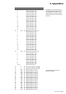
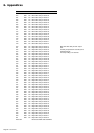
282 R Non-stored minor alarms
0 60% < Current in circuit 17 < 80%
1 60% < Current in circuit 18 < 80%
2 60% < Current in circuit 19 < 80%
3 60% < Current in circuit 20 < 80%
4 60% < Current in circuit 21 < 80%
5 60% < Current in circuit 22 < 80%
6 60% < Current in circuit 23 < 80%
7 60% < Current in circuit 24 < 80%
8 60% < Current in circuit 25 < 80%
9 60% < Current in circuit 26 < 80%
10 60% < Current in circuit 27 < 80%
11 60% < Current in circuit 28 < 80%
12 60% < Current in circuit 29 < 80%
13 60% < Current in circuit 30 < 80%
14 60% < Current in circuit 31 < 80%
15 60% < Current in circuit 32 < 80%
283 R Non-stored minor alarms
0 60% < Current in circuit 33 < 80%
1 60% < Current in circuit 34 < 80%
2 60% < Current in circuit 35 < 80%
3 60% < Current in circuit 36 < 80%
4 60% < Current in circuit 37 < 80%
5 60% < Current in circuit 38 < 80%
6 60% < Current in circuit 39 < 80%
7 60% < Current in circuit 40 < 80%
8 60% < Current in circuit 41 < 80%
9 60% < Current in circuit 42 < 80%
10 to 15 Unused bits (all set to 0)
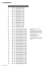
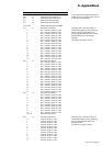
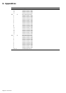
284 R Non-stored major alarms
0 Current in circuit 01 > 80%
1 Current in circuit 02 > 80%
2 Current in circuit 03 > 80%
3 Current in circuit 04 > 80%
4 Current in circuit 05 > 80%
5 Current in circuit 06 > 80%
6 Current in circuit 07 > 80%
7 Current in circuit 08 > 80%
8 Current in circuit 09 > 80%
9 Current in circuit 10 > 80%
10 Current in circuit 11 > 80%
11 Current in circuit 12 > 80%
6. Appendices
A value entered in the global parameters to
enable the 42 (or 21) output circuits to be set
to that value at the same time.
These bits go to 1 when the current in a
corresponding output circuit is greater than
the minor alarm threshold (60% in the
example opposite) and less than the major
alarm threshold (80% in the example
opposite).
This state is not stored in memory.
These bits go to 1 when the current in a
corresponding output circuit is greater than
the major alarm threshold (80% in the
example opposite).
This state is not stored in memory.