Installation and User Manual
Introduction 1 — 5
86-172010-00 C05
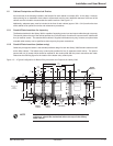
1.2 Cabinet Footprints and Electrical Entries
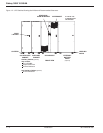
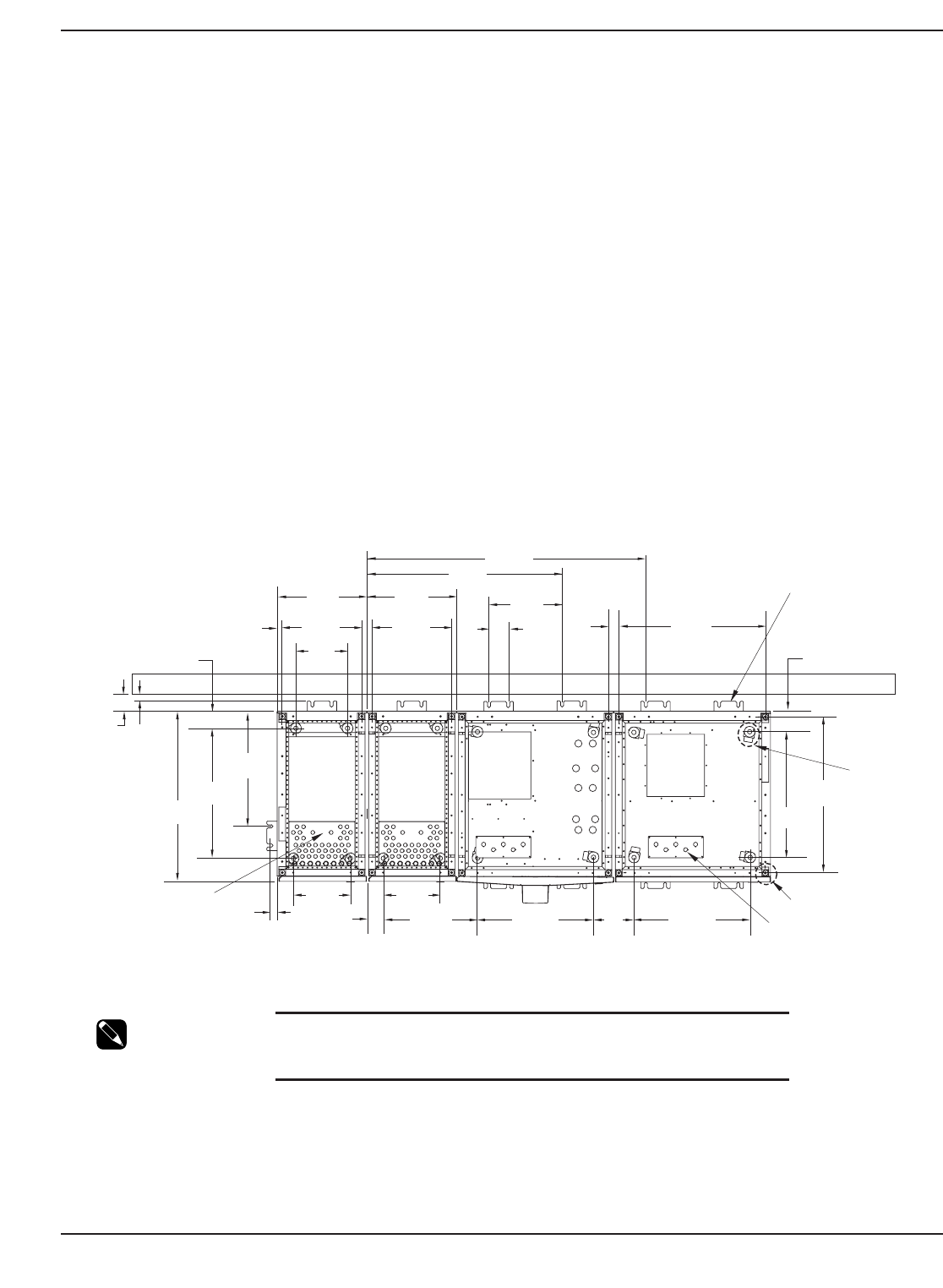
As can be seen in the following illustration, the footprint for each cabinet is nominally 36in - 914.4) deep. However,
when planning for an installation where seismic requirements must be met, additional clearance at the rear of the
cabinet must be included to accommodate the seismic anchors. See Figure 1-3.
Additionally, adequate space must be included in the front of each cabinet (approx .36in - 914.4) to allow the door
of the cabinet to be opened for service and maintenance procedures.
1.2.1 Conduit Plate Locations for top entry
The Standard cabinet for the Galaxy 3000 is capable of accepting power input and output cables through a top entry.
The conduit plate on the top of the cabinet provides six (6) knockouts for conduit and is secured to the cabinet with
four (4) machine screws. The standard Micro cabinet is supplied with bottom entry only, however, an optional side
mounted cable raceway can be specified to allow top entry for power connections.
1.2.2 Conduit Plate Locations (bottom entry)
Cable entry through the bottom is the standard preferred design for both the Galaxy 3000 Standard cabinet as well
as the Micro cabinet. The bottom entry conduit plate provides for five (5) separate conduit entries. The plate is
secured with six (6) screws which should be retained for the conduit plate after the power connections are made.
Please see the following figure for the location of the bottom entry conduit plate.
Figure 1-3: A Typical Configuration for Bottom Entry Knockouts and Footprints for Galaxy 3000.
NOTE
To provide for adequate ventilation, a minimum of 36in (914.4)
clearance should be maintained above the top of the Galaxy
3000 cabinet.
16.6in
(421.64)
10.8in
(274.32)
UPS Module
MINIMUM
DISTANCE
TO WALL
(with seismic)
24.0in
(609.60)
WALL
1.00in
(25.4)
4.50in
(114.3)
36.0in
(914.4)
18.8in
(477.52)
11.9in
(302.26)
1.1in
(27.94)
23.1in
(586.74)
24.2in
(614.68)
24.2in
(614.68)
8.4in
(213.36)
11.9in
(302.26)
58.2in
(1478.28)
2.2in
(55.88)
26.2in
(665.48)
1.1in
(27.94)
16.6in
(421.64)
30.6in
(777.24)
3.4in
(86.36)
25.5in
(647.70)
15.3in
(388.62)
18.8in
(477.52)
LEVELING
JACKS
CASTER
AIR INTAKE AIR INTAKEAIR INTAKEAIR INTAKE
SEISMIC
BRACKET
27.1in
(688.34)
Auxiliary
Cabinet
Auxiliary
Cabinet
(5) x .875
(TYPICAL)
4.0in
(TYP.)
(8) x .875 / 1.125
(38) x .875
32.6in
(828.04)
3.6in
(91.44)
4.3in
(109.22)
Dimensions in:
inches
(millimeters)


