Installation and User Manual
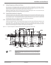
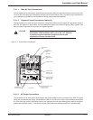
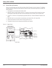
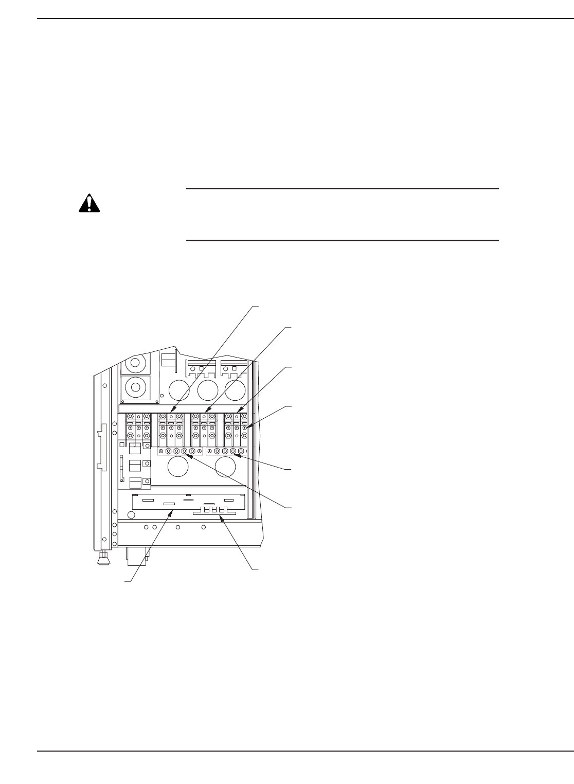
2.2.1.1 Main AC Input Connections
The connections to be made are the three phases, and ground cables from the utility AC power source to the UPS.
The main AC input cables are terminated at the Main Input Terminal Blocks (TB1). Complete wiring instructions for
your installation are provided on the installation drawings supplied with the equipment.
2.2.1.2 Bypass AC Input Connections (optional)
The connections to be made are the three phases, and ground cables from the bypass AC input power source to
the UPS. The bypass AC input cables are terminated at the Bypass Input Terminal Blocks (TB3) if present. This
option provides a separate AC input source for bypass operation.
CAUTION
Before making any electrical connections, verify that all battery
disconnect circuit breakers (QF1) are in the "off" position.
Customer-supplied upstream protective devices and
distribution circuits should be OFF.
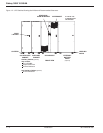
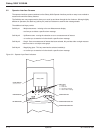
Figure 2-1: Typical Power Connections.
2.2.1.3 AC Output Connections
The connections to be made are the three phases, and ground cables from the load source to the UPS.The output
cables are terminated at the Output Terminal Blocks (TB2) for 15 kVA small module, and input/output connections
for 10-30 kVA large module. Load cables must be run separately from all other cables (power supply or computer-
system interconnection cables). They should not pass near interference-emitting equipment or sensitive loads.
Installation 2 — 3
86-172010-00 C05
UPS OUTPUT
(TB2)
(UTILITY2)
BYPASS INPUT
(TB3)
(OPTIONAL)
MAIN INPUT
CONNECTIONS
(TB1)
TERMINAL BLOCK
INPUT NEUTRAL
TERMINAL POST
1/4-20 X 3/4" DIA.
OUTPUT NEUTRAL
TERMINAL POST
1/4-20 X 3/4" DIA.
GROUND TERMINAL POSTS
(INPUT & OUTPUT)
1/4-20 X 3/4" DIA.
FRONT VIEW
BOTTOM ENTRY
CONDUIT PLATE


