2.3 Connecting Remote Emergency Power Off Cables
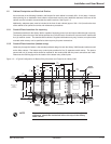
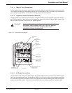
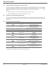
The control connections are available for Remote Emergency Power Off (REPO) through a customer-supplied
normally closed pushbutton.With REPO connected, the jumper on the REPO terminal blocks must be removed.The
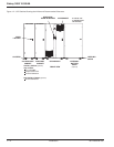
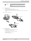
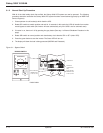
UPS is also equipped with a local Emergency Power Off button on the front of the UPS cabinet. See
Figure 2-1.
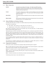
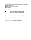
1. Remove the jumper from terminal block TB4 located across terminals 7 and 8.
2. Connect the emergency power off NC contact to terminals 7 and 8.
2.3.1 Connection of Relay Communication Card
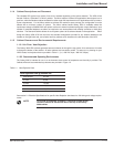
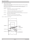
The relay communications card contains six programmable dry contact outputs and two programmable dry inputs
and is standard on the Galaxy 3000. The inputs and outputs are factory programmed according to functions listed
in Table 2-2.
Table 2-2: Relay Contacts (communications card).
Inputs Factor Setting Options (available on both contacts)
1.A UPS ON - Room temperature fault
- Transfer to bypass disabled
- Transfer to bypass disabled if Bypass AC
1.B UPS OFF source out of tolerance
- Desynchronize UPS from Bypass AC source
Outputs Factor Setting Options (available on all contacts)
1.1 General alarm - Overload
- PFC fault
- Inverter fault
1.2 Battery fault - Charger fault
- Automatic-bypass fault
- Bypass AC source out of tolerance
1.3 Load on UPS - Battery-temperature fault
- Fan fault
- Emergency power off activated
1.4 Load on automatic bypass - Battery circuit breaker(s) open
- Phase-sequence fault on Normal or Bypass
AC source
1.5 Load on battery power - Blown fuse(s)
- Transfer to Bypass AC source disabled
- Operation in ECO mode
1.6 Low battery warning - UPS on Bypass AC source
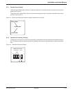
The indications 1.X become 2.X for a second card of the same type.
Galaxy 3000 10-30kVA
Installation2 — 4
86-172010-00 C05


