


86-108814-00 B01
Installation and Operation
2 — 5
Installation and User Manual
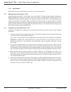
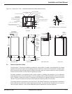
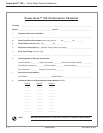
Figure 2-4: Power-Sure™ 700 — 225-300kVA Mechanical Cabinet Measurements.
2.4 General Operation Notes
The Power-Sure™ 700 Power Conditioners provides the triple function of isolation, noise attenuation and voltage
regulation. The first two functions are provided by the power transformer, where as the third function of voltage regula-
tion is achieved through solid state thyristors (SCRs) connected to taps on the power transformer. A micro-processor
monitors and controls the overall function of regulating the system.
The power transformer is manufactured with a unique method of shielding which produces very low capacitive
coupling between the primary and secondary. This low coupling provides excellent attenuation of the common-mode
noise. In addition, special care is taken in the design of the transformer to attenuate transverse-mode noise above
1000 Hz. The power transformer has taps to which solid state switches (SCRs) are connected.
The voltage regulator incorporated in the Power-Sure™ 700 Power Conditioners is microprocessor controlled to
achieve optimum correction time of input voltage sags and surges. The response time is typically one (1/2) cycle for
100% correction, therefore, a very smooth switch takes place undetected by computer equipment.
41.5"
(1054.1m)
77.207"
(159.9m)
35"
(889m)
2.75"
(69.85m)
56"
(1422.4m)
50.5"
(1282.7m)
2.75"
(69.85m)
32"
(1812.8m)
POWER ON
ALERT
INPUT
CIRCUIT
BREAKER
(TERMINATE
INPUT
CABLES
AT CIRCUIT
BREAKER)
OPTIONAL
BYPASS
SWITCH
(OPEN
DOOR
FOR
ACCESS)
CLEARANCE
HOLE
FOR 1/2"
MOUNTING
BOLT
LEFT SIDE VIEW FRONT VIEW RIGHT SIDE VIEW
REAR VIEW
G N L3 L2 L1
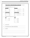
5.5" (139.7m)
3.25" (82.55m)
4.625"
(117.47m)
OUTPUT TERMINAL DETAIL .25 X 4 COPPER BUSS
5.25" (133.35m)
4.625"
(117.47m)
1.75" (44.45m)
1.73" (43.94m)
1" (25.4m)
1" (25.4m)
2" (50.8m)
32"
(1812.8m)
OUTPUT
TERMINALS
CUSTOMER
SIDE
TOP VIEW
LIFT-OFF
ACCESS PANEL
9" (228.6m)
45"
(1143m) Clearance
CABINET COOLING FAN
LIFT-OFF
ACCESS PANEL
OUTPUT CONDUIT LOCATION
INPUT CONDUIT LOCATION
8" (203.2m)
8" (203.2m)
5" CLEARANCE REQUIRED
(THIS SIDE)
OUTPUT ACCESS PLATE
OUTPUT TERMINALS
LIFT-OFF ACCESS PANEL
6" CLEARANCE REQUIRED
(THIS SIDE)
36" CLEARANCE REQUIRED
(THIS SIDE)
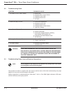
EDGE FRAMING
FOR SCREENING
(18 GAGE .047 THICK STEEL)
LAYER 2
LAYER 1
EDGE FRAMING
FOR SCREENING
(18 GAGE .047 THICK STEEL)
LAYER 1
METAL –
(1.47D X 1.47W , 120 THICK)
LAYER 2
METAL (GALVANIZED STEEL –
(1.25D X 1.25W , 120 THICK)