


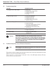

NOTE: When checking the power module assembly, if more than one defective power
module is present it will appear as if all the power modules are defective.
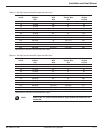
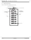
The individual power module must be isolated from the power transformer:
◗ K1-1 to K2-1 thru K1-7 to K2-7 = High resistance, 1 Meg Ohm.
◗ K1-1 to G1-1 thru K1-7 to G1-7 = 10 to 90 Ohms.
◗ K1-1 to G2-1 thru K1-7 to G2-7 = 1 Meg Ohm.
◗ K2-1 to G2-2 thru K2-7 to G2-7 = 10 to 90 Ohms.
◗ K2-1 to G1-1 thru K2-7 to G1-7 = 1 Meg Ohm.
◗ G1-1 to G2-1 thru G1-7 to G2-7 = 1 Meg Ohm.
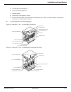
4. Replace any defective power modules. This may require removing the shunt and loosening the K1 bus from all
the power modules to get the defective power module out. Use only equivalent hardware and heat sink grease
when replacing power modules.
5. If a resistance measure is questionable, a more thorough test will assure an SCR is good or bad.
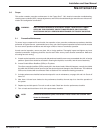
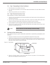
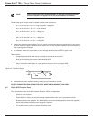
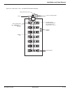
Test procedure:
◗ Completely isolate SCR under test by removing all connections to the device.
◗ Hook up the following test circuit to each individual SCR.
◗ Plug in SCR tester. With Switch #1, open light bulb should be off. If not, replace SCR.
◗ Close Switch #1. Light bulb should illuminate to about 3/4 brilliance. If not, replace SCR.
Figure 3-2: Test Wire Diagram.
6. Reassemble the power module assembly, making sure all connections are tight.
DO NOT CONNECT THE SEMI-CONDUCTOR FUSE, WIRES OR FAN WIRES AT THIS POINT.
3.5 Check SCR Snubber Card
Three components make up the SCR snubber: Resistors, MOVs and Capacitors.
◗ Check for open resistors.
◗ Check MOVs for shorts, they should read high resistance when ohm meter is placed across them.
◗ Resistance check each capacitor. The DC resistance across the snubber capacitor should look capacitive,
that is high resistance after the meter charges the capacitor.
◗ If it measures open or shorted, replace the snubber card.
Switch
#1
1 K 1 WATT
Power-Sure™ 700 —
Three Phase Power Conditioners
3 —6
86-108814-00 B01
Maintenance