


Maintenance
3 —17
Installation and User Manual
FORMULA X
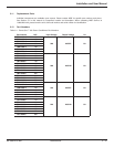
AC Input x 2.47 = Volts DC at TP2
480 (Nominal)
Example: 475 Volts AC Input x 2.47 = 2.44 Volts DC at TP2
480 (Nominal)
NOTE: Be sure AC input is stable when making this adjustment. If the input changes,
you must re-calculate.
7. After calculations are complete, place DC voltmeter on 20 volt scale and check between TP2 and TP GND on
control card. Adjust pot P1 so meter reads DC level calculated in Step 6 for all 3 phases.
NOTE: Output voltage correction is a “stepped correction”, adjusting P1 will not cause
a smooth change in output voltage as it is adjusted.
8. Turn unit off and reconnect TB2 connectors on all control boards.
9. Turn unit on and verify output is correct by monitoring the output from each line to neutral.
If output is not correct, make sure input power is stable and repeat adjustment procedure.
NOTE: P1 Pot turned clockwise = decrease in output voltage and counter-clockwise =
increase in output voltage. By changing this adjustment on 1 phase you may see
the output voltage change from line to neutral on 2 phases. It is best to use
procedures in Steps 1-9 when adjusting.
3.9.3 Over/Under Voltage Detection Board #35867
NOTE: Adjustments are referenced from the units output.
3.9.3.1 Undervoltage Adjustment
1. The under voltage adjustment can be adjusted from -1% (118.5 VAC) to -20% (95 VAC) The standard
setpoint is -10% (108 VAC).
2. P2 will adjust the undervoltage set point. One turn on P2 will change the voltage level approximately
1 volt.
Clockwise = Increase in sensitivity.
Counter-clockwise = Decrease in sensitivity.
3.9.3.2 Overvoltage Adjustment
1. The over voltage adjustment can be adjusted from +1% (121 VAC) to +20% (145 VAC).
The standard set point is +10% (132 VAC).
86-108814-00 B01