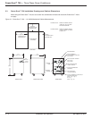
1.4.3 Input Breaker
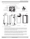
Main input molded case circuit breaker, rated at 125% of full load input current.
1.5 Monitoring the Power-Sure™ 700
Monitoring of the Power-Sure™ 700 is simple, clean, and effective. Three green light indicators are utilized to
display “POWER ON” (output line to neutral for each phase) and one red light indicator to display “ALERT”. The
“POWER ON” display is connected directly to the output that indicates the Power-Sure™ 700 is operating properly
with just a quick glance. The “ALERT” display represents an overtemp problem or output voltage loss (optional)
when illuminated, and will shut down the output, but cooling fans remain on. Overtemp thermal sensors are strate-
gically located at critical points on the regulator assemblies and transformer. The main AC input circuit breaker must
be turned off in order to reset the “ALERT” light.
1.6 Protection for the Power-Sure™ 700
Protection is accomplished very effectively to minimize failures and the cost of repairs by the four major methods
listed below:
1. The input is protected with a integrally mounted AC circuit breaker for abnormal current overloads and provides
a convenient means of disconnecting utility power.
As an option, the input breaker may be equipped with a shunt trip device that is interfaced with a REMOTE
EMERGENCY POWER OFF PUSH BUTTON. By pressing this button, the input breaker will trip and
disable the Power-Sure™ 700 completely. The input breaker must be physically reset before unit will
turn on again.
2. The electronic regulating devices are protected with fast acting semi-conductor fuses. These fuses are
designed to clear before damage occurs to the more expensive SCR regulating devices. The main transformer
is protected by fuse links connecting the SCR regulators together, and are designed to clear in the event that
two or more SCRs should fail. This will prevent a transformer tap short and the possibility of transformer failure.
3. When provided with the optional Under/Over Voltage Shutdown Card (UOV2020), the output of the
Power-Sure™ 700 is constantly monitored for extreme over and under voltage conditions. This card monitors
each output phase and will electronically disable the Power-Sure™ 700 when any phase exceeds +10% or
-10% of nominal output voltage.
4. Overtemp sensing devices are mounted at critical points on the SCR regulating assembly and the main trans-
former. When an overtemp condition exists the “ALERT” light will illuminate and hold until the overtemp is
corrected. There are no automatic shutoff circuits for the “ALERT” condition. The main AC input breaker must
be turned off in order to reset the “ALERT” light.
Introduction - Protection
Power-Sure™ 700 —
Three Phase Power Conditioners
1 — 4
86-108814-00 B01


