


Contents
c iii
Installation and User Manual
Figures
figure description . . . . . . . . . . . . . . . . . . . . . . . . . . . . . . . . . . . . . . . . . . . . . . . . .page
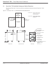
2-1: Power-Sure™ 700 — 10-15kVA Mechanical Cabinet Measurements . . .2 — 2
2-2: Power-Sure™ 700 — 25-30kVA Mechanical Cabinet Measurements . . .2 — 3
2-3: Power-Sure™ 700 — 45-150kVA Mechanical Cabinet Measurements . .2 — 4
2-4: Power-Sure™ 700 — 225-300kVA Mechanical Cabinet Measurements .2 — 5
3-1: Power Module . . . . . . . . . . . . . . . . . . . . . . . . . . . . . . . . . . . . . . . . . . . . .3 — 5
3-2: Test Wire Diagram . . . . . . . . . . . . . . . . . . . . . . . . . . . . . . . . . . . . . . . . . .3 — 6
3-3: Power-Sure™ 700 — 10-15kVA Major Components . . . . . . . . . . . . . . . .3 — 9
3-4: Power-Sure™ 700 — 25-30kVA Major Components (Rear View) . . . . . .3 — 9
3-5: Power-Sure™ 700 — 45-150kVA Major Components (Rear View) . . . .3 — 10
3-6: Power-Sure™ 700 — 225-300kVA Cable Connections,
Input Output Locations. . . . . . . . . . . . . . . . . . . . . . . . . . . . . . . . . . . . . .3 — 11
3-7: Power-Sure™ 700 — 10-30kVA SCR Heatsink Assembly . . . . . . . . . .3 — 12
3-8: Power-Sure™ 700 — 45-50kVA SCR Heatsink Assembly . . . . . . . . . .3 — 13
3-9: Power-Sure™ 700 — 75-150kVA SCR Heatsink Assembly . . . . . . . . .3 — 14
3-10: Power-Sure™ 700 — 225-300kVA SCR Heatsink Assembly . . . . . . . .3 — 15
3-11: Power-Sure™ 700 Controller Card (Top View) . . . . . . . . . . . . . . . . . . .3 — 16
Tables
table description . . . . . . . . . . . . . . . . . . . . . . . . . . . . . . . . . . . . . . . . . . . . . . . . .page
2-1: 480 VAC Input and 208 VAC Output Wire Size Chart . . . . . . . . . . . . . . .2 — 7
2-2: 208 VAC Input and 208 VAC Output Wire Size Chart . . . . . . . . . . . . . . .2 — 7
3-1: Power-Sure™ 700 Power Conditioners Part Numbers . . . . . . . . . . . . .3 — 19
86-108814-00 B01