


CAUTION: THE CONTROL BOARD (#49120/407415) IS ELECTRICALLY REFERENCED TO
HIGH VOLTAGE, NOT EARTH OR CHASSIS GROUND. EXTREME CARE MUST BE
USED WHEN TAKING MEASUREMENTS ON THE CONTROL BOARD. ANY AC
POWERED INSTRUMENTS MUST BE GROUND ISOLATED PRIOR TO TAKING
MEASUREMENTS. A GROUND ISOLATED INSTRUMENT CASE WILL BE AT THE
HIGH VOLTAGE LINE POTENTIAL.
3.9.2 Control Card Adjustment Procedure
1. Prior to attempting any adjustment, measure the incoming voltage to the unit. Assure the voltage level is within
the specified input range of the unit.
2. Turn off power to unit.
3. Remove all loads from the output of unit under adjustment.
4. Remove both TB2 connectors on all control boards #49120/407415. Turn power on.
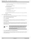
5. With DC voltmeter on the millivolt scale check between TP1 and TP GND and adjust P2 so meter reads “0”
millivolts or as close as possible.
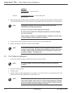
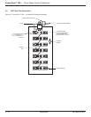
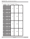
Figure 3-11: Power-Sure™ 700 Controller Card (Top View).
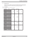
6. Use Formula X below to calculate the next adjustments. You must calculate each input phase for each control
card or a total of 3 calculations:
◗ For phase 1 control card, measure AC input at Line 1 to Line 2.
◗ For phase 2 control card, measure AC input at Line 2 to Line 3.
◗ For phase 3 control card, measure AC input at Line 1 to Line 3.
115V
208V
240V
TP
GND
TP1
TP2
GRND
P2
TB2
TB2
TB2
TB3
P1
49120 /
407415
1
17
1
Maintenance
Power-Sure™ 700 —
Three Phase Power Conditioners
3 —16
86-108814-00 B01