


Maintenance
3 —7
Installation and User Manual
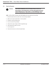
RE-CONNECT SEMI-CONDUCTOR FUSE, AND ALL WIRES AND FANS. DOUBLE CHECK THAT ALL CONNEC-
TIONS ARE SECURE.
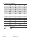
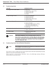
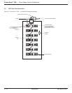
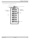
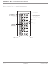
NOTE: Control board #49120 is for 10kVA to 50kVA units. Control board
#407415 is for 75kVA and larger.
DO NOT CONNECT TB1, TB2, and TB3 CONNECTORS FROM THE CONTROL CARDS #49120/407415 YET!
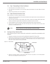
3.5.1 Check Control Card and Filter Card
1. Verify input to the conditioner matches the units specification. Also verify correct control board #49120 / 407415
jumper setup. See Figure 3-11, Page 3-16.
2. Disable the over/under voltage shutdown card #35867 (optional card) by removing connectors K1 and K2 on
the card.
3. Turn on AC input breaker to unit.
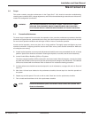
IMPORTANT: Extreme caution must be taken when measuring voltages on Molex connectors.
Do not press meter leads into connectors or bend connectors back.
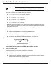
4. Measure the following voltages on wires feeding the TB1 Molex connector to the control card on all 3 phases.
Pins 1 & 3 = 4-6 VAC.
Pins 7 & 8 = 120 VAC
NOTE: When the connector is plugged in, this voltage is around 3 VAC.
If this voltage is incorrect or not present, then check the fuses associated with the filter card or replace filter card
and re-check voltages.
5. Turn main AC circuit breaker off. Plug in connectors TB1 and TB3 ONLY on the control card #49120/407415 on
all 3 phases.
6. Turn main AC on. With DC voltmeter on the millivolt scale check between TP1 and TP GND of the control card
and adjust pot P2 so meter reads “0” millivolts or close as possible.
NOTE: This step does not apply to Control Board #407415.
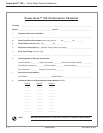
7. Use the following formula to calculate the next adjustments. You must calculate each input phase for each
control card or a total of 3 calculations.
◗ For phase 1, control card measures AC input at Line 1 to Line 2.
◗ For phase 2, control card measures AC input at Line 2 to Line 3.
◗ For phase 3, control card measures AC input at Line 1 to Line 3.
86-108814-00 B01