


Maintenance
3 —5
Installation and User Manual
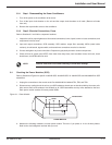
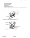
3.3.1 Step 1. Disassembling the Power Conditioners
1. Turn off the power to the conditioner at its source.
2. Turn off the input circuit breaker on the unit and the output circuit breakers to all loads. (Remove all loads
from unit).
3. Remove the top and side covers to the conditioner.
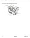
3.3.2 Step 2. Electrical Connections, Fuses
Refer to Sections 3.7 and 3.8 for component locations.
1. Inspect the unit for proper tightness of all electrical connections, burnt, frayed, broken or loose connections, and
components in these areas.
2. Input and output connections, SCR assembly, SCR snubber, output filter assembly, MOVs (metal oxide
varistors), circuit boards, bypass switch, and transformer connections need to be checked.
3. Correct and tighten any loose connections. Replace any physically burned or broken components.
4. Check all fuses in system (see NOTE). Also check time delay fuses, semi-conductor fuses, fan fuses, circuit
board fuses, and SCR fusible link wire.
NOTE: Remove fuses from circuit when checking to avoid false readings.
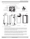
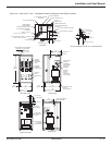
3.4 Checking the Power Modules (SCR)
Refer to Section 3.8 Figures for specific 10-30kVA SCR, 45-50kVA SCR, 75-150kVA SCR, and 225-300kVA for SCR
assemblies.
1. Unplug the connections to the control cards Part #49120/407415 labeled TB1, TB2, and TB3.
2. Disconnect any cooling fans in the unit so your SCR resistance checks are not interfered with by fan motor coils.
Also remove main semi-conductor fuse located on all 3 SCR assemblies and any wires attached to the fuse.
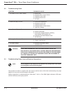
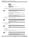
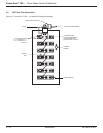
Each power module contains 2 inverse parallel SCRs.
Figure 3-1: Power Module.
3. Measure the following resistance on each power module. There are 7 per phase or 21 for all three phases.
Refer to the circuit diagrams received with your unit.
G1
G2
SHUNT
TRANSFORMER
POWER MODULE
86-108814-00 B01