


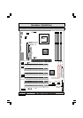
The P4X4-ALH Mainboard
Page 16
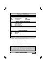
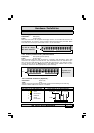
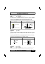
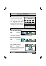
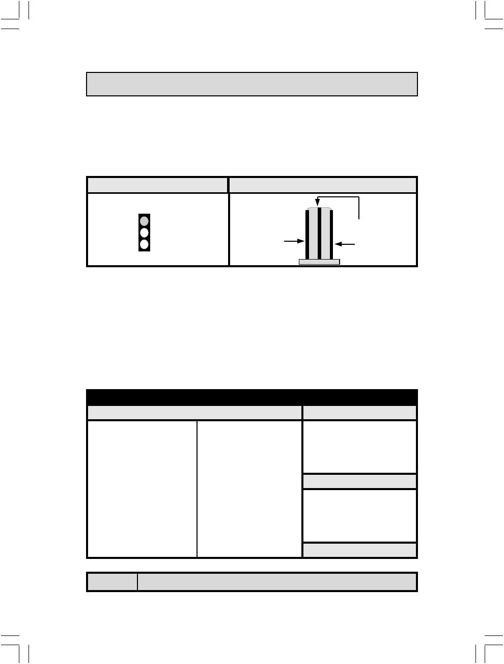
2.5.4. CPU Fan and Chassis Fan Connectors
Connector: CN13 (FAN1)/CN17 (FAN2)
Type: 3 pin
The cooling fans must be connected to their respective power connectors. If
you have installed the hardware-monitoring feature you will be able to monitor
the rotating speed of the CPU cooling fan in your Windows operating system.
Hardware Installation
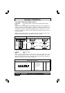
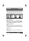
ATX Connectors Pin Assignments
CN15-A CN15-B
Pin 1 +3.3VDC Pin 11 +3.3VDC Pin 1 COM
Pin 2 +3.3VDC Pin 12 -12VDC Pin 2 COM
Pin 3 COM Pin 13 COM Pin 3 +12VDC
Pin 4 +5VDC Pin 14 PS_ON# Pin 4 +12VDC
Pin 5 COM Pin 15 COM
CN15-D
Pin 6 +5VDC Pin 16 COM
Pin 1 +12VDC
Pin 7 COM Pin 17 COM Pin 2 COM
Pin 8 PWR_OK Pin 18 -5VDC Pin 3 COM
Pin 9 +5VSB Pin 19 +5VDC Pin 4 +5VDC
Pin 10 +12VDC Pin 20 +5VDC
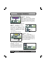
Fan Signal
+12V DC
Ground
1 Ground
2 +12V DC
3 Fan Signal
Top View of a Fan Connector Front View of a Fan Connector
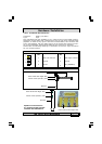
2.5.5. ATX Power Supply Connectors
Connector: CN15-A/CN15-B/CN15-D
Type: 20 pin block/2x2 12V/1x4 AUX12V
The mainboard comes with three onboard power supply connectors labeled
CN15-A, CN15-B and CN-15D. CN15-A and CN15-B are regular ATX12V power
supply connectors. CN15A and CN15D are regular ATX power supply connec-
tors. The auxiliary power supply connector (CN15-D) is for a +12V and +5V
power supply. These increased power supplies are necessary to provide extra
power for the slot. The ATX 12V power supplies are all downward compatible
with standard ATX power supplies.