


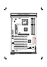

The P4X4-ALH Mainboard
Page 20
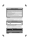
2.6.1 PW: Power On/Off and External Suspend Switch Connector
The Power On/Off connector has two functions. It can be the Power Switch or
Suspend Switch of your PC system. You can either choose “Delay 4 Sec” or
“Instant OFF” .
Option 1:
If you choose “
Delay 4 Sec.
” In the BIOS CMOS Setup, the func-
tion of “PW” will be:
A. When the system power is "OFF", press this switch, the system will
power on.
B. When system power is "ON”, you can select two different modes: -
Mode 1: Press and hold the Power ON button for less than 4 seconds and then
release it. The system will be turned into Suspend mode (turned into the
GREEN mode) When the system is in the Suspend mode:
Press the Power on button (less than 4 seconds), the system will return
to Full-ON mode.
Press and hold the Power On Button for more than 4 seconds, the sys-
tem will be powered off.
Mode 2:
Press and hold the Power ON button for more than 4 seconds, the
system will be completely powered off.
Option 2: If you choose “Instant OFF.” In the BIOS CMOS Setup, the power
switch will operate like a normal ON / OFF Power button.
2.6.2. SL: Sleep LED Connector
When lighted, the LED indicates that the AC power is ON but your system is
switched OFF. When unlighted, the LED indicates that either the AC power is
OFF/Unconnected or the system is switched ON.
2.6.3. HL: IDE HDD LED Connector
Any read and write activity by the HDD will turn this LED on.
2.6.4. RS: Reset Button Connector
If you connect this connector, you will be able to reset you computer by press-
ing the reset button at the front of the chassis.
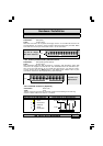
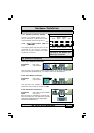
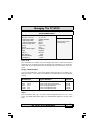
Hardware Installation
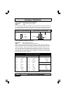
2.6. System Panel Buttons and LED Connectors
The following System Panel Buttons and
LED Connectors (2 x 4 pins) can be
found at the front of the mainboard on
the left hand side.
PW= Power On/Off and Suspend Switch
Connector
SL = Sleep LED Connector
HL = HDD LED Connector
RS = Reset Button Connector
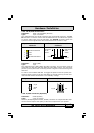
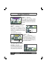
Top View of the System Panel
and LED Connectors
PIN 1
SL: Signal Pin
HL: +5V DC Pull Up
PW:+5V DC Pull Up
Ground
Ground
Ground
RS: Reset Control
Ground