


4-6
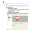
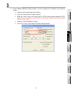
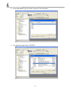
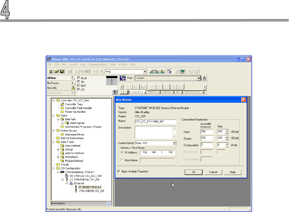
4. Double Click on the selection and configure the ICC module accordingly. This is a critical
configuration step to ensure the ETH-1000 will work properly in the system as the application
requires. Please also consult the ICC ETH-1000 User’s Manual carefully about the configuration of
these items.
a. Configure the “Comm Format” as “Data-INT” for the overall system to work best with the
ICC module and the controller registers. This will allow the transfers to be done in 16 bit
integers.
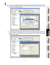
• Note: For each application, the data type should be configured to match the
requirements of the particular application.
b. Set the IP Address of the generic Ethernet module to the IP address assigned to the ICC
module earlier. For example, the IP address of the ICC module is set at 192.168.1.102 In
the Verification System.
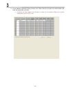
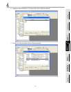
c. Configure the “Connection Parameters” as follow:
• The “Input” Assembly Instance should be set at “150.” The size of the Input
Assembly buffers should be set at the size appropriate for the application. In the
verification system, the buffer is set at 248 16-bit words.
• The “Output” Assembly Instance should be set at “100.” The size of the Input
Assembly buffers should be set at the size appropriate for the application. In the
verification system, the buffer is set at 248 16-bit words.
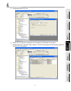
• The “Configuration” is not used and should be set at “1” as the Assembly
Instance and 0 buffer size.
d. Check the “Open Module Properties” box and click “OK” to accept the configuration.