


4 Power supply
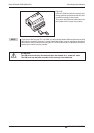
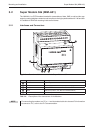
After all installation steps are completed, switch on the power supply to the Mitsubishi Alarm
Modem. The modem got two power supply connectors: Two screw terminals and a power sup
-
ply jack (pin diameter 2,1 mm, inner diameter 6 mm).
E
ATTENTION:
Power U = 10 – 40V DC! for Mitsubishi Normal Modem (MIM-G01)
Power U = 10 – 30V DC! for Mitsubishi Super Modem (MIM-A01)
Ensure the correct polarity of the power supply terminals.
NOTE In order to avoid the interference from power supply units or other interference sources,
DC cables should not be installed in the direct vicinity of AC cables.
P
DANGER:
Power supply
Mitsubishi Industrial Modem 4-1
b
Use leads with sufficient diameter only.
b
Do not use flexible leads with soldered tips.
b
Watch the polarity and the specification of the power supply.
(MIM-G01=10 – 40VDC, max. 0.7 A, Power supply jack: pin = positive)
(MIM-A01=10 – 30VDC, max. 0.7 A, Power supply jack: pin = positive)
b
In order to avoid damages, fasten the terminal screws with a torque momentum
of 0.5 ... 0.6Nm.
b
When using the power supply jack, make sure the plug got an
pin diameter of 2.1mm and inner diameter of 6mm.
b
Wiring must be done with power off only.