


5 Operation
If you have followed the steps in the chapters 3 and 4, your modem is ready for operation.
5.1 MIM-G01
The MIM-G01 presents two LEDs, which indicate the devices current operating mode. After the
power supply hasbeen switched on, a self test will be executed. The endof this testis indicated
by aacoustic signal(short beep). Afterthetest, thedevice tries tomake aconnection tothe GSM
network. The green LED will flash slowly when the log in was successful..
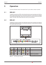
5.2 MIM-A01
The MIM-A01 presents five LEDs, which indicate the devices current operating mode. After the
power supply hasbeen switched on, a self test will be executed. The endof this testis indicated
by a acoustic signal (short beep).
MIM-G01 Operation
5-1 MITSUBISHI ELECTRIC
COM1
(RS232)
-+
DC 10...30V
Service
Power
Line
Mail in
Mail out ModemMode
SUPER MODEM
56k
COM1
(RS232)
-+
DC 10...30V
Service
Line
Mail in
Mail out ModemMode
SUPER MODEM
56k
COM1
(RS232)
-+
DC 10...30V
Service
Power
Line
Mail in
Mail out Modem Mode
COM1
(RS232)
-+
DC 10...30V
Service
Line
Mail in
Mail out Modem Mode
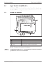
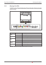
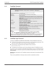
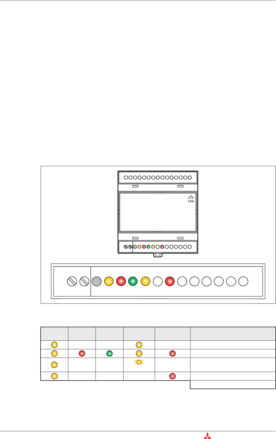
Fig. 5-1: LEDs on MIM-A01
Power
(yellow)
Mail in
(red)
Line
(green)
Mail out
(yellow)
Modem Mode
(red)
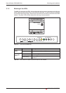
Starting self test
Testing LEDs
Flashes
Testing memory
Modem is fully operational
Duration: approx. 12 sec
Tab. 5-1: LEDs during the self-test