


11 - 24 11 - 24
MELSEC-Q
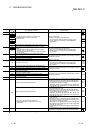
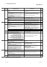
11 TROUBLESHOOTING
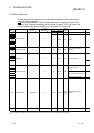
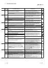
Error Code
(SD0)
1
Error Contents and Cause Corrective Action
Corres-
ponding
CPU
Slot loaded with the QI60 is set to other than the Inteli (intelligent
function module) or Interrupt (interrupt module) in the parameter I/O
assignment.
Make setting again to match the parameter I/O assignment with the
actual loading status.
QCPU
function
Ver. B
or later
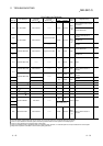
(1) In the parameter I/O allocation settings, an Inteli (intelligent
function module) was allocated to a location reserved for an I/O
module or vice versa.
(2) In the parameter I/O allocation settings, a module other than
CPU (or nothing) was allocated to a location reserved for a CPU
module or vice versa.
(3) A general-purpose switch was set to the module with no
general-purpose switches.
(1) Reset the parameter I/O allocation setting to conform to the
actual status of the intelligent function module and the CPU
module.
(2) Delete the general-purpose switch settings.
QCPU
Rem
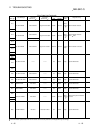
2100
In parameter I/O allocation settings, a special function module was
allocated to a location reserved for an I/O module. Or, the opposite
has happened.
Reset the parameter I/O allocation setting to conform with the actual
status of the special function modules.
QnA
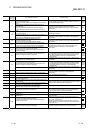
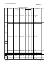
13 or more A-series special function modules (except for the QI60,
A1SI61) that can initiate an interrupt to the CPU module have been
installed.
Keep the number of A-series special function modules that can
initiate an interrupt (except for the QI60, A1SI61) to 12 or fewer.
QCPU
2101
13 or more special function modules (not counting the AI61)
capable of sending an interrupt to the CPU module have been
installed.
Keep the number of special function modules that can initiate an
interrupt (with the exception of the AI61 module) to 12 or fewer.
QnA
7 or more A1SD51S have been installed. Keep the number of A1SD51S to 6 or fewer. QCPU
2102
7 or more computer link modules (excludes A (1S) J71QC24) have
been installed.
Keep the number of computer link modules (excludes A (1S)
J71QU24) installed to 6 or fewer.
QnA
Rem
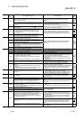
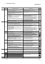
(1) Two or more QI60/A1SI61 modules are loaded in a single-PLC
system.
(2) Two or more QI60/A1SI61 modules are set to the same control
PLC in a multiple CPU system.
(3) Two or more A1SI61 modules are loaded in a multiple CPU
system.
(1) Reduce the number of QI60/A1SI61 modules loaded in the
single-PLC system to one.
(2) Change the number of QI60/A1SI61 modules set to the same
control PLC to only one in the multiple CPU system.
(3) Reduce the number of A1SI61 modules to only one in the
multiple CPU system.
When using an interrupt module with each QCPU in a multiple
CPU system, change it for the QI60. (Use one A1SI61 module +
max. three QI60 modules or only the QI60 modules.)
QCPU
function
Ver. B
or later
Two or more QI60, A1SI61 interrupt modules have been installed. Install only 1 QI60, A(1S)I61 module. QCPU
The QI60 is loaded. Remove the QI60. Rem
2103
Two or more AIS61 interrupt modules have been installed. Install only 1 AI61 module. QnA
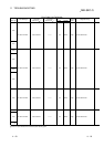
2104
At the MELSECNET/MINI auto refresh parameter settings, the
module allocation that was set is different from the actual module
models at the station numbers in the link system.
Reset the parameter MELSECNET/MINI auto refresh unit module
allocation setting so that it conforms to the station number of the
module that is actually linked.
QnA
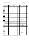
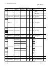
2105
There are too many special function modules that can use
dedicated instructions allocated (number of modules installed).
(The total of the figures indicated below is above 1344.)
(Number of AD59 modules installed × 5)
(Number of AD57 (S1)/AD58 modules installed × 8)
(Number of AJ71C24 (S3/S6/S8) modules installed × 10)
(Number of AJ71UC24 modules installed × 10)
(Number of AJ71C21 (S1) modules installed × 29)
(Number of AJ71PT32-S3/AJ71T32-S3 modules installed × 125)
(Number of AJ71QC24 (R2, R4) modules installed × 29)
(Number of AJ71ID1 (2)-R4 modules installed × 18)
(Number of AD75 modules installed × 12)
Total > 1344
Reduce the number of special function modules installed.
: When the expansion mode is used.
QnA
• Five or more MELSECNET/H modules are loaded in a whole
multiple CPU system.
• Five or more Q series Ethernet interface modules are loaded in a
whole multiple CPU system.
Reduce the number of modules to four or less in the whole multiple
CPU system.
QCPU
function
Ver. B
or later
(1) 5 or more MELSECNET/H modules have been installed.
(2) 5 or more Q series Ethernet interface modules have been
installed.
(3) Identical network numbers or station numbers exist in the
MELSECNET/10 network system.
(1) Keep the number to 4 or fewer.
(2) Keep the number to 4 or fewer.
(3) Check the network numbers and station numbers.
QCPU
Rem
2106
(1) 5 or more AJ71QLP21 & AJ71QBR11 modules are installed.
(2) 3 or more AJ71AP21/R21 & AJ71AT21B modules are installed.
(3) The total number of installed AJ71QLP21, AJ71QBR11,
AJ71AP21/R21, and AJ71AT21B modules exceeds 5.
(4) Identical network Nos. or identical station Nos. exist at the
MELSECNET/10 network system.
(5) 2 or more master or load stations exist simultaneously at the
MELSECNET(II) or MELSECNET/B data link system.
(1) Install 4 or fewer modules.
(2) Install 2 or fewer modules.
(3) Reduce the total number of modulees to 4 or less.
(4) Check the network Nos. and station Nos.
(5) Check the station Nos.
QnA
2107
Head X/Y set in the parameter I/O allocation settings is also the
head X/Y for another module.
Reset the parameter I/O allocation setting to conform with the actual
status of the special function modules.
Rem
(1) Network module A1SJ71LP21, A1SJ71BR11, A1SJ71AP21 ,
A1SJ71AR21, or A1SJ71AT2B
dedicated for the A2USCPU
has been installed.
(2) Network module A1SJ71QLP21 or A1SJ71QBR11 dedicated for
the Q2AS has been installed.
Change network module to QJ71LP21 or QJ71BR11. QCPU
2108
A(1s)J71LP21 or A(1s)J71BR11 for use with the AnUCPU network
module has been installed.
Change network module to A(1s)J71QLP21 or A(1s)J71QBR11. QnA
2109 6
The control system and standby system module configurations are
different when a redundant system is in the backup mode.
Check the module configuration of the standby system. Q4AR
1 Characters in parentheses ( ) indicate the special register numbers where individual information is being stored.
6 This can only be detected in the redundant system standby system.