


6 - 8 6 - 8
MELSEC-Q
6 BASE UNIT AND EXTENSION CABLE
6.6 Guideline for Use of Extension Base Units (Q5
B)
Since the Q5
B is supplied with 5VDC from the power supply module on the main
base unit, a voltage drop occurs at extension cables.
Improper I/O may be provided if the specified voltage (4.75VDC or higher) is not
supplied to the "IN" connector of the Q5
B.
When using the Q5
B, make sure that the "IN" connector of the Q5
B is supplied
with 4.75VDC or higher.
And it is recommend to connect it with the shortest possible extension cable right after
connecting the main base unit, so as to minimize the effects of voltage drop.
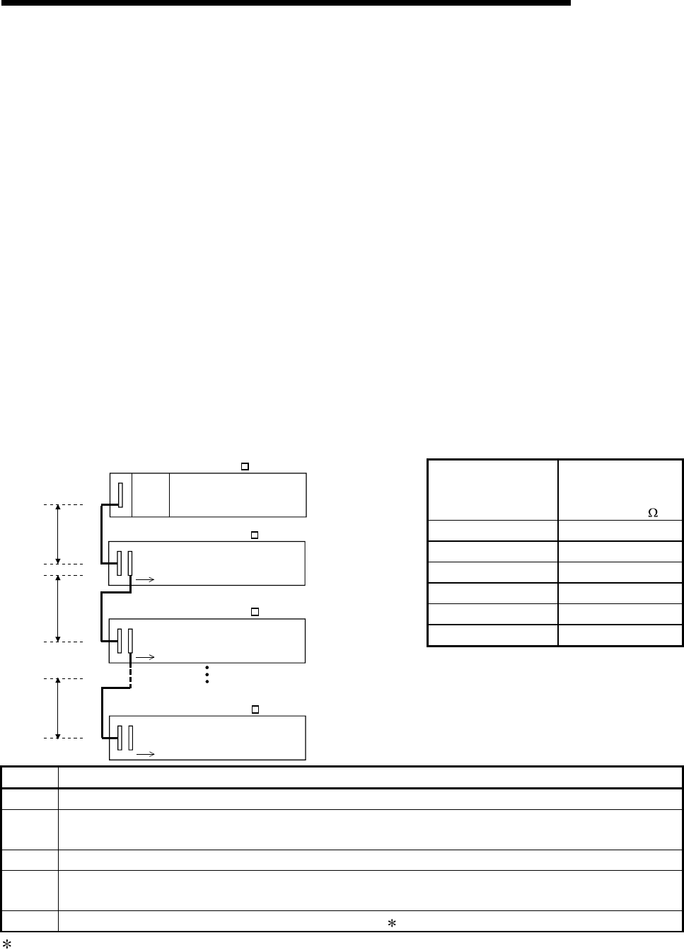
(1) When only the Q5
B is connected to the extension base unit
(a) Selection condition
4.75VDC or higher should be supplied to the "IN" connector of the Q5
B in
the final extension stage.
(b) How to calculate voltage to "IN" connector
The 5VDC output voltage of the power supply module on the main base
unit is set to at least 4.90VDC.
Therefore, the Q5
B can be used if the voltage drop is 0.15VDC or lower
(4.9VDC - 4.75VDC = 0.15VDC).
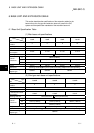
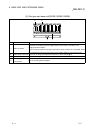
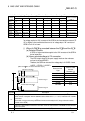
Extension Cable
Type
Extension Cable
Conductor
Resistance (
)
QC05B 0.044
QC06B 0.051
QC12B 0.082
QC30B 0.172
QC50B 0.273
QC100B 0.530
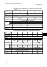
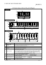
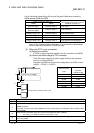
V1
V2
R7
R1
R2
R7
Power
supply
module
Extension stage 1
Extension stage 2
Extension stage 7
Main base unit (Q3 B)
Extension base unit (Q5 B)
Extension base unit (Q5 B)
Extension base unit (Q5 B)
l1
l2
l7
Symbol Description
V1 Voltage drop at the extension cable between the main base unit and extension base unit
Vn
Voltage drop at the extension cable between the extension base unit (extension stage n-1) and extension base
unit (extension stage n)
R1 Cable resistance between the main base unit and extension base unit
Rn
Cable resistance between the extension base unit (extension stage n-1) and extension base unit (extension
stage n)
l1 to l7 5VDC current consumption among extension stage 1 to 7 1
1: Sum total of current consumed by Q5
B and currents consumed by the I/O, intelligent function modules loaded on the
Q5
B.
The symbols including "I" (I1 to I7) vary with the modules loaded on the extension base unit. For details of the symbol,
refer to the user's manuals of the module used.