


9 - 15 9 - 15
MELSEC-Q
9 LOADING AND INSTALLATION
9.3.3 Installation and removal of module
This section explains how to install and remove a power supply, CPU, I/O, intelligent
function or another module to and from the base unit.
(1) Installation and removal of the module from Q3 B, ,Q5 B and
Q6 B
The installation and removal of the module from Q3 B/Q6 B base unit are
described below.
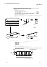
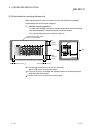
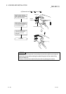
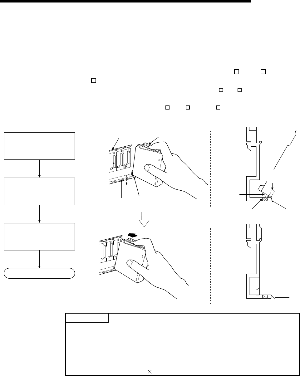
(a) Installation of module on Q3
B, Q5 B and Q6 B
Module
Module fixing latch
Module fixing
hole
Module
connector
Base unit
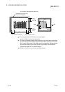
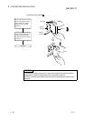
Base unit
Module loading
lever
Module
fixing latch
Module fixing hole
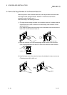
Insert the module fixing latch
into the module fixing hole of
the base unit.
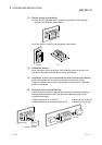
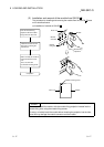
Push the module in the
direction of arrow to load it
into the base unit.
Make sure that the module
is inserted in the base unit
securely.
Completion
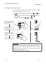
POINTS
(1) Always insert the module fixing latch of the module into the module fixing hole.
Forcing the hook into the hole will damage the module connector and module.
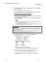
(2) When using the PLC in a place where there is large vibration or impact, screw
the CPU module to the base unit.
Module fixing screw : M3
12 (user-prepared)