


11 - 38 11 - 38
MELSEC-Q
11 TROUBLESHOOTING
11.5 I/O Module Troubleshooting
This chapter explains possible problems with I/O circuits and their corrective actions.
11.5.1 Input circuit troubleshooting
This section describes possible problems with input circuits and their corrective
actions.
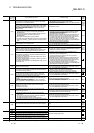
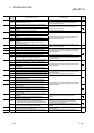
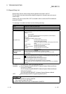
Input Circuit Problems and Corrective Actions
Condition Cause Corrective Action
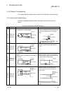
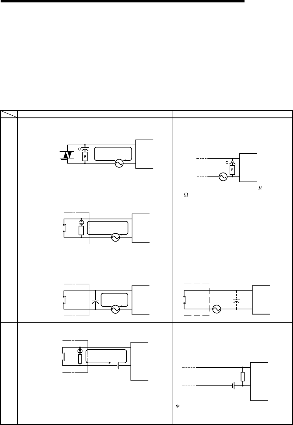
Example 1
Input signal
does not
turn OFF.
• Leakage current of input switch
(e.g. drive by non-contact switch).
Leakage
current
Input module
AC input
Power supply
• Connect an appropriate resistor which will
make the voltage across the terminals of the
input module lower than the OFF voltage
value.
AC input
Input module
It is recommended to use 0.1 to 47
F + 47 to
120
(
1/2W
)
for the CR constant.
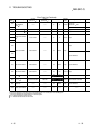
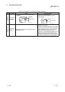
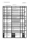
Example 2
Input signal
does not
turn OFF.
• Drive by a limit switch with neon lamp.
Leakage
current
AC input
Input module
Power supply
• Same as Example 1.
• Or make up another independent display
circuit.
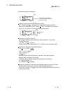
Example 3
Input signal
does not
turn OFF.
• Leakage current due to line capacity of wiring
cable.
(Line capacity C of twisted pair wire is approx.
100 pF/m).
Leakage
current
AC input
Input module
Power supply
• Same as Example 1.
• However, leakage current is not generated
when the power supply is located in the input
equipment side as shown below.
AC input
Input module
Power supply
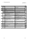
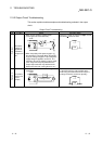
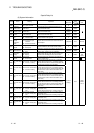
Example 4
Input signal
does not
turn OFF.
• Drive by switch with LED indicator.
Leakage
current
DC input
(plus common
)
Input module
• Connect a register which will make the voltage
between the input module terminal and
common lower than the OFF voltage, as
shown below.
DC input
(plus common
)
Input module
Resistor
A calculation example of a value for a
connected resistor is given on the following
page.