


11 - 36 11 - 36
MELSEC-Q
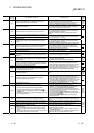
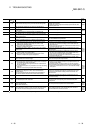
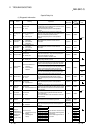
11 TROUBLESHOOTING
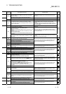
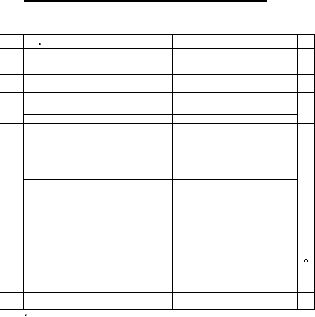
Error Code
(SD0)
1
Error Contents and Cause Corrective Action
Corres-
ponding
CPU
6100 A CPU module tracking memory error was detected during initial.
Because this is a CPU module hardware error, contact your nearest
Mitsubishi representative.
To replace the module, replace the standby system CPU first, then
the control system CPU.
6101
The CPU module detected an error during the handshake for
tracking.
Check the condition of the other stations.
Q4AR
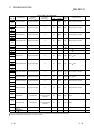
6200
The standby system in a redundant system is switched to the
control system.
Check the control system condition.
6210
The control system in a redundant system is switched to the
standby system.
Check the control system condition.
Q4AR
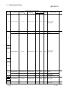
6220
The standby system in a redundant system could not be switched
from the control system to the standby system because of an error
status or other reason.
Check the standby system condition.
6221 Switching is disabled because of a bus switching module error.
Because this is a bus switching module hardware error, contact
your nearest Mitsubishi representative.
6222
Switching is disabled because a multiplexed master station of a
remote I/O network was installed in the standby station during initial.
Check the remote I/O network setting.
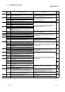
(1) In a multiple CPU system, at CPU module fault occurred at a
station where "all station stop by stop error of PLC " was
selected in the operating mode.
(2) High Performance model QCPU of function version A was
loaded in a multiple CPU system.
(1) Read the error individual information at a peripheral device,
check the error of the PLC resulting in CPU module fault, and
remove the error.
(2) Remove the High Performance model QCPU of function version
A from the main base unit.
7000
In a multiple CPU system, station 1 resulted in stop error at power-
on and the other stations cannot start. (This error occurred at
stations 2 to 4)
Read the error individual information at a peripheral device, check
the error of the CPU module resulting in CPU module fault, and
remove the error.
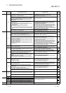
7002
(1) There is no response from the target station in a multiple CPU
system at initial communication stage.
(2) High Performance model QCPU of function version A was
loaded in a multiple CPU system configuration.
(1) Reset the High Performance model QCPU and run it again. If
the same error is displayed again, it is a hardware fault of any
CPU module. Consult your sales representative.
(2) Remove the High Performance model QCPU of function version
A from the main base unit.
7003
There is no response from the target station in a multiple CPU
system at initial communication stage.
Reset the High Performance model QCPU and run it again. If the
same error is displayed again, it is a hardware fault of any CPU
module. Consult your sales representative.
QCPU
function
Ver. B
or later
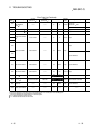
7010
(1) Faulty CPU is loaded in a multiple CPU system.
(2) High Performance model QCPU of function version A is loaded
in a multiple CPU system configuration.
(An error is detected at the High Performance model QCPU of
function version B.)
(3) In a multiple CPU system, any of stations 2 to 4 was reset during
power-on.
(This error occurs at only the station which was reset.)
(1) Read the error individual information at a peripheral device, and
change the faulty station.
(2) Change the station of function version A for function version B.
(3) Do not reset the CPU modules of PLC No.2 to 4. Reset the High
Performance model QCPU of PLC No.1 and restart the multiple
CPU system.
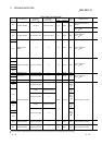
7020
In a multiple CPU system, a PLC fault occurred at a station where
"all station stop by stop error of PLC" was not selected in the
operation mode.
(The error is detected at the High Performance model QCPU of
other than the station where the CPU module fault occurred.)
Read the error individual information at a peripheral device, check
the error of the CPU module resulting in CPU module fault, and
remove the error.
QCPU
function
Ver. B
or later
9000 Annunciator F was set ON
Read the error individual information at a peripheral device, and
check the program corresponding to the numerical value
(annunciator number).
9010 Error detected by the CHK instruction.
Read the error individual information at a peripheral device, and
check the program corresponding to the numerical value (error
number) there.
9020
Storage of data onto ROM was completed normally in automatic
write to standard ROM.
(BOOT LED also flickers.)
Set the parameter enable drive to standard ROM, switch power on
again, and perform boot operation from standard ROM.
QCPU
function
Ver. B
or later
10000
In the multiple CPU system, an error occurred in the CPU module
other than the Process CPU/High Performance model QCPU.
Use the software package of the corresponding CPU module to
check the details of the error that occurred.
QCPU
function
Ver. B
or later
1 Characters in parentheses ( ) indicate the special register numbers where individual information is being stored.