


10 - 8 10 - 8
MELSEC-Q
10 MAINTENANCE AND INSPECTION
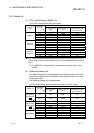
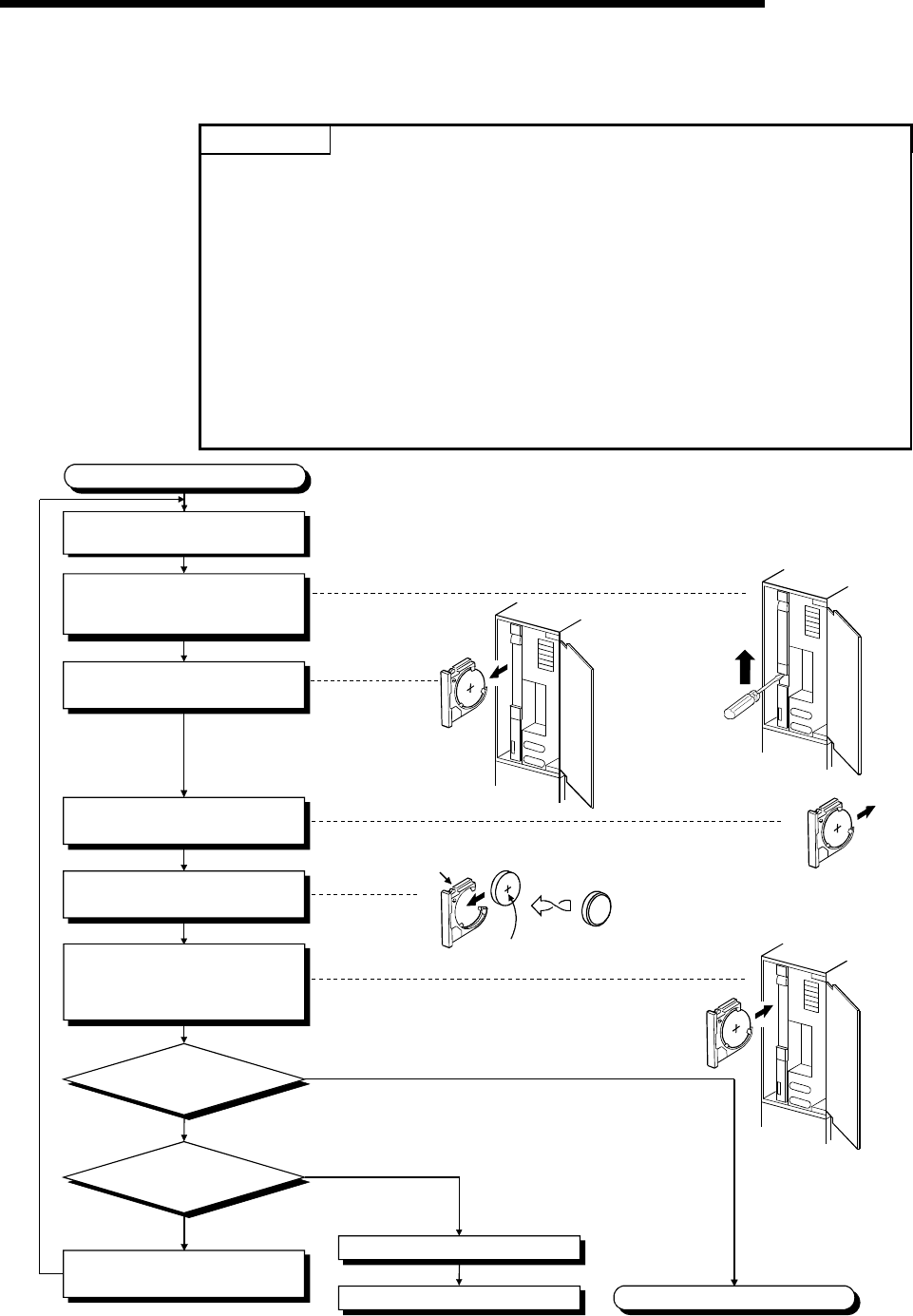
(2) SRAM card CPU module battery replacement procedure
Replace the SRAM card battery in the following procedure.
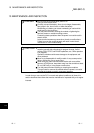
POINTS
Replace the battery while paying attention to the following.
(a) To back up the data, replace the SRAM card battery with the PLC power supply
ON and the SRAM card installed.
(b) Start replacement after backing up the CPU module data using GX Developer.
(c) Since replacement is made with the PLC power supply ON, take extreme care
not to get an electric shock.
(d) When dismounting or mounting the battery holder on the SRAM card, take care
so that the battery does not come out of the battery holder.
(e) When replacing the battery with the PLC power supply OFF, always back up the
data before starting replacement.
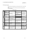
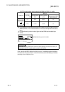
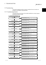
[Battery replacement procedure]
1) Back up the SRAM card data using GX Developer.
2) Replace the battery.
3) Write the backed up data from GX Developer to the memory card.
Completion
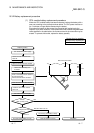
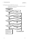
Monitor
SM52 to verify on/off.
Monitor
SD52 to verify the bit number
that is on.
The CPU module battery is faulty.
Refer to Section 10.3.2 (1).
Bit 0 is on.
A bit other than 0 is on
ON
OFF
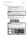
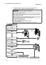
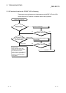
Replacing battery
Using a flat screw-driver, slide the
battery holder's locking switch
away from the "LOCK" position.
Remove the battery holder from
the SRAM card.
Remove the old battery from
its holder.
Insert a new battery into the holder
in the correct direction.
Push the battery holder all the way
into the memory card, and confirm
that the battery holder's locking
switch is set to the "LOCK" position.
"RELEASE"
position
'+' sign
Open the front cover while the
PLC power supply is on.
Bit 1 or 2 on:
Memory card A battery is faulty.
Battery holder