


11 - 87 11 - 87
MELSEC-Q
11 TROUBLESHOOTING
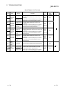
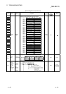
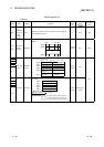
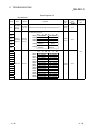
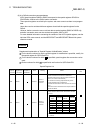
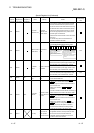
Special Register List (Continued)
ACPU
Special
Conversion
Special
Register after
Conversion
Special
Register for
Modification
Name Meaning Details
Corresponding
CPU
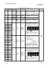
D9002 SD1002
I/O module
verification error
I/O module
verification error
module number
• If I/O modules, of which data are different from data
entered, are detected when the power is turned on,
the first I/O number of the lowest number unit among
the detected units is stored in hexadecimal. (Storing
method is the same as that of SD1000.) To monitor
the number by peripheral devices, perform monitor
operation given in hexadecimal.
(Cleared when all contents of SD1116 to SD1123 are
reset to 0.)
• I/O module verify check is executed also to the
modules of remote I/O terminals.
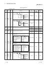
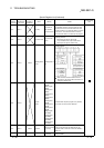
D9004 SD1004
MINI link master
module errors
Error detection
state
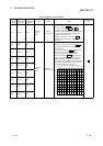
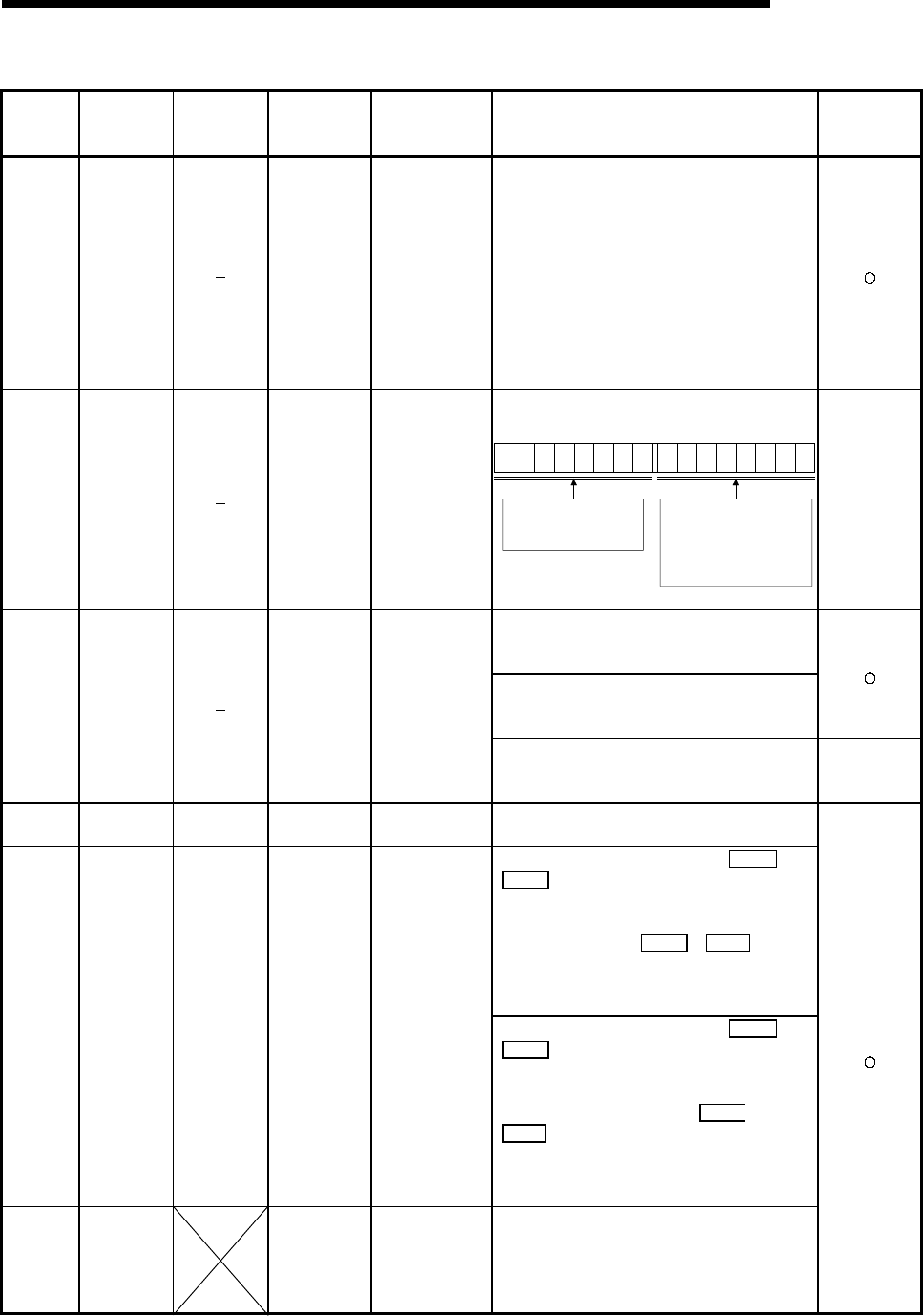
• Stores the MINI(S3) link error detection status in the
mounted MELSECNET/MINI-S3 master module.
B15 B8 B7 B0
8765
4
32
18
7
65
4
32
1
Bits which correspond to the signals of
A(1S)J71PT32(S3), shown below, are
turned on as the signals are turned on.
· Hardware error (X0/X20)
· MINI(S3) link error datection (X6/X26)
· MINI(S3) link communication error
(X7/X27)
to to
On the PLC CPU and
A(1S)J71PT32(S3) side, the bit
corresponding to the
A(1S)J71PT32(S3) that cannot
make data communication turns ON.
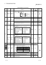
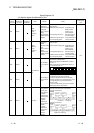
QnA
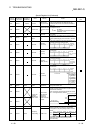
• Turned ON if instantaneous power failure of within
20ms occurs when AC power supply module is used,
and reset when power is switched OFF, then ON.
• Turned ON if instantaneous power failure of within
10ms occurs when DC power supply module is used,
and reset when power is switched OFF, then ON.
D9005 SD1005
AC DOWN
counter
Number of times for
AC DOWN
• Turned ON if instantaneous power failure of within
1ms occurs when DC power supply module is used,
and reset when power is switched OFF, then ON.
QnA
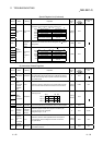
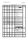
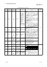
D9008 SD1008 SD0
Self-diagnosis
error
Self-diagnosis error
code
• When error is found as a result of self-diagnosis, error
code is stored in BIN code.
• When one of F0 to 2047 is turned on by OUT F or
SET F , the F number, which has been detected
earliest among the F numbers which have turned on,
is stored in BIN code.
• SD62 can be cleared by RST F or LEDR
instruction.
If another F number has been detected, the clearing of
SD62 causes the next number to be stored in SD62.
D9009 SD1009 SD62
Annunciator
detection
F number at which
external failure has
occurred
• When one of F0 to 2047 is turned on by OUT F or
SET F , the F number, which has been detected
earliest among the F numbers which have turned on,
is stored in BIN code.
• SD62 can be cleared by executing RST F or
LEDR instruction or moving INDICATOR RESET
switch on CPU front to ON position. If another F
number has been detected, the clearing of SD62
causes the nest number to be stored in SD62.
D9010 SD1010 Error step
Step number at
which operation
error has occurred.
• When operation error has occurred during execution
of application instruction, the step number, at which
the error has occurred, is stored in BIN code.
Thereafter, each time operation error occurs, the
contents of SD1010 are renewed.