


11 - 72 11 - 72
MELSEC-Q
11 TROUBLESHOOTING
Special Register List (Continued)
Number Name Meaning Explanation
Set by
(When set)
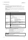
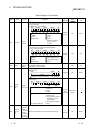
Corresponding
ACPU
D9
Corresponding
CPU
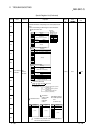
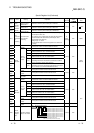
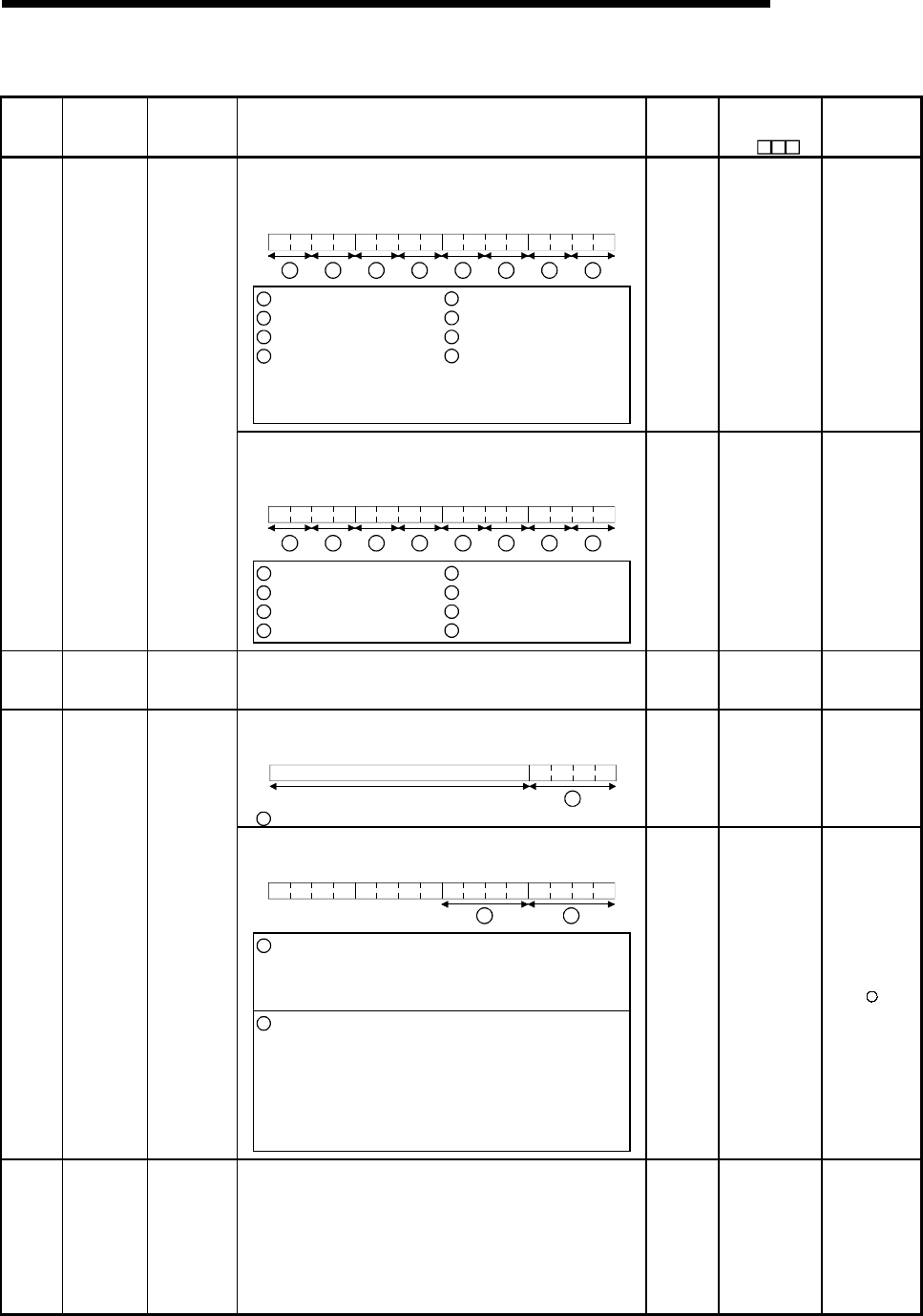
• The following bit patterns are used to store the statuses of the LEDs
on the CPU module:
• 0 indicates OFF, 1 ON, and 2 flicker.
B15
B12
B11 B8B7 B4B3 B0
8
3 2
1
456
7
1
: RUN
2
: ERROR
3
: USER
4
: BAT.ALARM
5
: BOOT
6
: Vacant
7
: Vacant
8
: MODE
Bit patterns for MODE
0: OFF, 1: Green,
2: Orange
S (Status
change)
New QCPU
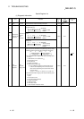
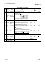
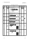
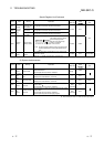
• Information concerning which of the following status the LEDs on the
CPU module are in is stored in the following bit patterns:
• 0 is off, 1 is on, and 2 is flicker
B15
B12
B11
B8
B7 B4
B3 B0
8
3 2
1
456
7
1
: RUN
2
: ERROR
3
: USER
4
: BAT.ALARM
5
: BOOT
6
: CARD A (Memory card)
7
: CARD B (Memory card)
8
: Vacant
SD201 LED status
Status of
CPU-LED
S (Status
change)
New QnA
SD202 LED off
Bit pattern of
LED that is
turned off
• Stores bit patterns of LEDs turned off
(Only USER and BOOT enabled)
• Turned off at 1, not turned off at 0
U New QnA
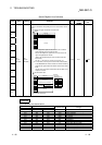
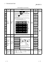
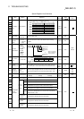
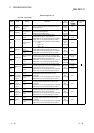
• The operating status of the remote I/O module is stored in the
following format.
B15 B4B3 B0
1
Vacant
1
Remote I/O module operating status Always 2: STOP
S (Always) New Remote
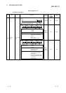
• The CPU module operating status is stored as indicated in the
following figure:
B15 B12B11 B8 B7 B4B3 B0
2
1
1
: Operating status of CPU 0 :RUN
1 :STEP-RUN
2 :STOP
3 :PAUSE
2
: STOP/PAUSE cause 0 :Switch
1 :Remote contact
2 : Remote operation from the
GX Developer or Serial
Communication.
3 :Internal program instruction
Note: Priority is earliest first 4 :Errors
SD203
Operating
status of
CPU
Operating
status of CPU
S (Every
END
processing)
D9015 format
change
SD206
Device test
execution
type
0: Test not yet
executed
1: During X
device test
2: During Y
device test
3: During X/Y
device test
• Set when the device test mode is executed on GX Developer.
S
(Request)
New Remote