


Index - 2 Index - 2
[P]
Performance................................................... 4- 1
Power supply module
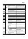
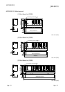
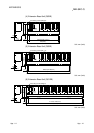
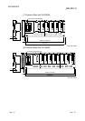
External dimensions diagram.................App- 7
Example of wiring ...................................... 9-25
Installation.................................................. 9-14
Names of parts and settings ...................... 5- 8
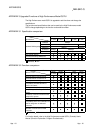
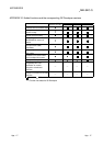
Specifications.............................................. 5- 1
Wiring......................................................... 9-22
Processing speed........................................... 4- 1
Programming language.................................. 4- 1
[Q]
QA1S65B, QA1S68B
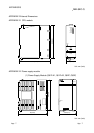
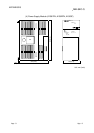
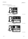
External dimensions...............................App- 9
Names of parts ........................................... 6- 6
Specifications.............................................. 6- 2
QC05B, QC06B, QC12B, QC30B, QC50B,
QC100B ......................................................... 6- 3
Q32SB, Q33SB, Q35SB
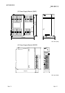
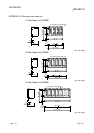
External dimensions..............................App-11
Names of parts ........................................... 6- 5
Specifications.............................................. 6- 1
Q33B, Q35B, Q38B, Q312B
External dimensions................................App-9
Names of parts ........................................... 6- 4
Specifications.............................................. 6- 1
Q Series.........................................................A-19
[R]
Remote RUN/PAUSE contact ....................... 4- 3
[S]
Specifications
Base unit..................................................... 6- 1
Battery......................................................... 7- 2
CPU............................................................. 4- 1
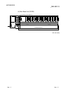
Extension cable .......................................... 6- 2
General ....................................................... 3- 1
Memory card............................................... 7- 1
Power supply module................................. 5- 1
System configuration
Configured equipment................................ 2- 1
Outline......................................................... 2- 4
Peripheral device........................................ 2- 3
[T]
Tightening torque of screw .............................9- 9
Total number of instructions ...........................4- 1
[W]
Weight
Base unit......................................................6- 1
Battery .........................................................7- 2
CPU .............................................................4- 3
Extension cable...........................................6- 3
Memory card ...............................................7- 1
Power supply module..................................5- 2
Wiring
Extension cable...........................................2- 3
Heat generation...........................................9- 6
I/O module..................................................9-24
Power supply module........................ 9-22,9-25
Wiring of the I/O module ............................9-24
Ind