


11 - 11 11 - 11
MELSEC-Q
11 TROUBLESHOOTING
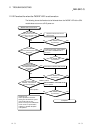
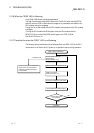
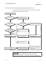
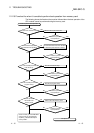
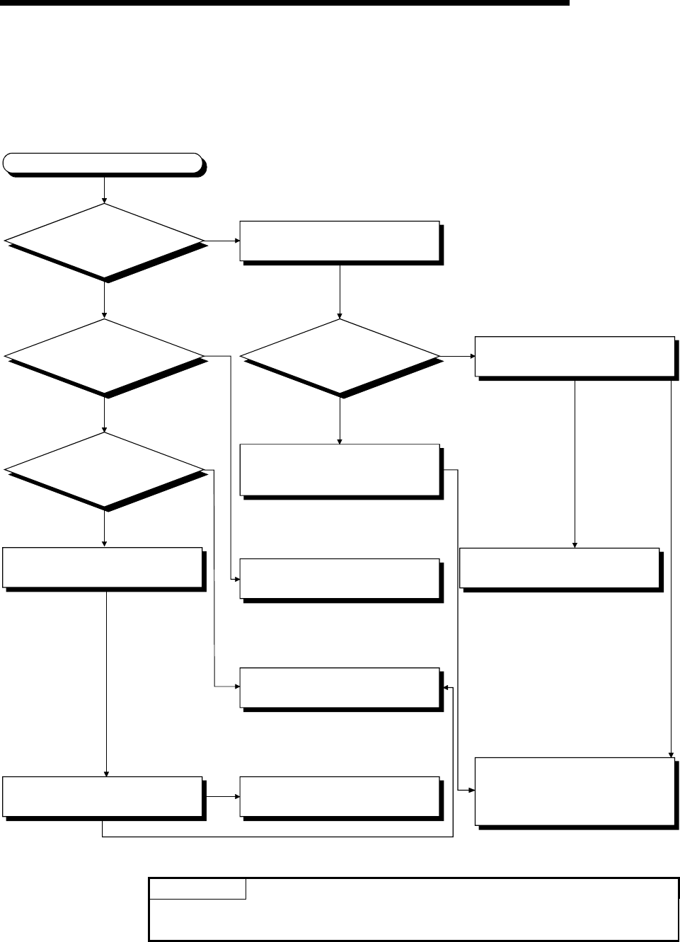
11.2.12 Flowchart for when output load of output module does not turn on
The following shows the flowchart to be followed when the output load of the output
module does not turn on during PLC operation.
Check output conditions with the
monitor mode of the GX Developer.
Is the operation
indicator of input module
turned on?
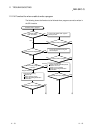
Check the power supply load wire
and recover the power supply.
Check the load wire and load, and
recover the power supply.
Change the output relay number and
let the load maximum simultaneous
on current to within the specification.
Voltage measurement among the
modules input and COM terminals.
Check the external wiring and
external input devices.
The output load does not turn on.
Is the operation
indicator of output module
turned on?
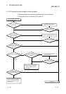
Is voltage for the
power supply load
added?
What is the voltage
among the various output
COM terminals of the
output module?
Output module failure
Replace the output module.
Confirm rush current when the load
is at the maximum simultaneous on.
YES
NO
NO
YES
0V
NG
OK
Is it reaching the
supply voltage
value?
On
Off
0V
(Monitor signal off)
Supply voltage
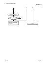
Set the GX Developer in the monitor
mode and check that the input signal
is OFF.
Please consult your local Mitsubishi
service center or representative,
explaining a detailed description
of the problem.
POINT
For the trouble that the input signal to the input module is not turned off,
troubleshoot referring to Section 11.5 Examples of I/O Modules Troubleshooting.