


11 - 91 11 - 91
MELSEC-Q
11 TROUBLESHOOTING
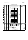
Special Register List (Continued)
ACPU
Special
Conversion
Special
Register after
Conversion
Special
Register for
Modification
Name Meaning Details
Corresponding
CPU
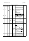
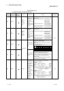
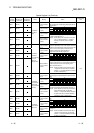
D9085 SD1085
Register for
setting time
check value
1s to 65535s
• Sets the time check time of the data link instructions
(ZNRD, ZNWR) for the MELSECNET/10.
• Setting range: 1 s to 65535 s (1 to 65535)
• Setting unit: s
• Default value: 10 s (If 0 has been set, default
10 s is applied)
D9090 SD1090
Microcomputer
subroutine input
data area head
device No.
According to
corresponding
microcomputer
package
• For details, refer to the manual of each microcomputer
program package.
D9091 SD1091
Detailed error
code
Self-diagnosis
detailed error code
• Stores the detail code of cause of an instruction error.
D9094 SD1094 SD251
Head I/O
number for
replacement
Head I/O number
for replacement
• Stores upper 2 digits of the head I/O address of I/O
modules to be loaded or unloaded during online mode
in BIN code.
Example) Input module X2F0
→
H2F
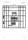
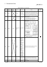
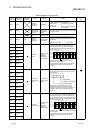
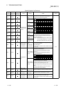
D9100 SD1100
D9101 SD1101
D9102 SD1102
D9103 SD1103
D9104 SD1104
D9105 SD1105
D9106 SD1106
D9107 SD1107
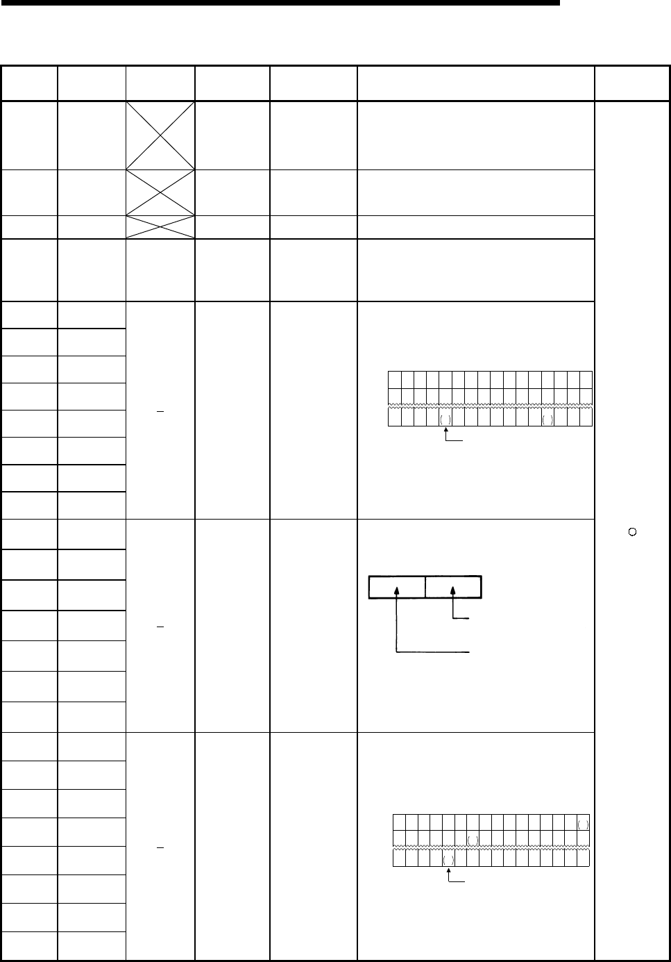
Fuse blown
module
Bit pattern in units
of 16 points,
indicating the
modules whose
fuses have blown
• Output module numbers (in units of 16 points), of
which fuses have blown, are entered in bit pattern.
(Preset output unit numbers when parameter setting
has been performed.)
15 14 13 12 11 10 9 8 7 6 5 4 3 2 1 0
00000000
1
(Y80)
000000
0000000000000000
00000000000000
1
Y7
B0
S
D1100
S
D1101
S
D1107
1
(YCO)
Indicates fuse blow.
1
Y7
30
• Fuse blow check is executed also to the output
module of remote I/O station.
(If normal status is restored, clear is not performed.
Therefore, it is required to perform clear by user
program.)
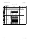
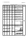
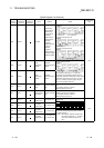
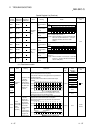
D9108 SD1108
D9109 SD1109
D9110 SD1110
D9111 SD1111
D9112 SD1112
D9113 SD1113
D9114 SD1114
Step transfer
monitoring timer
setting
Timer setting valve
and the F number
at time out
• Sets value for the step transfer monitoring timer and
the number of F which turns on when the monitoring
timer timed out.
Timer setting
(1 to 255 s in seconds)
F number setting
b15 b8 b7 b0to to
(By turning on any of SM1108 to SM1114, the
monitoring timer starts. If the transfer condition
following a step which corresponds to the timer is not
established within set time, set annunciator (F) is
tuned on.)
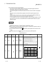
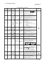
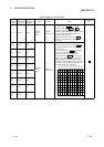
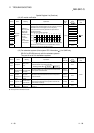
D9116 SD1116
D9117 SD1117
D9118 SD1118
D9119 SD1119
D9120 SD1120
D9121 SD1121
D9122 SD1122
D9123 SD1123
I/O module
verification error
Bit pattern, in units
of 16 points,
indicating the
modules with
verification errors.
• When I/O modules, of which data are different from
those entered at power-on, have been detected, the
I/O unit numbers (in units of 16 points) are entered in
bit pattern. (Preset I/O unit numbers when parameter
setting has been performed.)
15 14 13 12 11 10 9 8 7 6 5 4 3 2 1 0
0000000000000
000000000000000
00000000000000
1
XY
100
SD1116
SD1117
SD1123
1
XY
0
1
XY
100
0
00
Indicates I/O module verify error.
• I/O module verify check is executed also to remote I/O
station modules.
(If normal status is restored, clear is not performed.
Therefore, it is required to perform clear by user
program.)